
Repair Chevrolet Repair Toyota Repair Honda Repair AvtoVAZ Repair Mercedes-Benz Repair BMW Repair Opel
Home  |  Contacts  |  Sitemap  |    
English Русский
Български
Беларускі
Український
Српски
Hrvatski
Română
Polski
Slovenský
Magyar
AudiManual.ru


  • AUDI 80
  • AUDI 100
  • AUDI A3
  • AUDI A4
  • AUDI A6
  • AUDI A8
  • AUDI Q
  • OTHER
  • ARTICLES
B4 (1991-1996) B3 (1986-1991) B3 (1986-1991, petrol) B2 (1979-1986)

Camshaft and tappets — removal, inspection and installation (Audi 80 B3)

  • Home
  • Audi 80
  • B3 (1986-1991, petrol)
  • Power unit
  • Engine 4-cylinder
  • Camshaft and tappets — removal, inspection and installation
            0
1. If the hydraulic lifters are noisy when the engine is at normal operating temperature, the following method will help you identify the faulty lifter. Intermittent noises when starting a cold engine are normal.

2. Start the engine and warm it up to normal operating temperature until the electric cooling fan comes on.

3. Run the engine for two minutes to 2500 rpm, check the tappet noise. If the noise remains, continue as follows after stopping the engine.

4. Remove the valve cover, then rotate the crankshaft until the cam lifter being tested points straight up.

5. Using a non-metallic tool, press the plunger down. If the free play is more than 0.1 mm before the valve starts to open, the plunger must be replaced as follows.

6. Remove the air cleaner or fuel injection system components as described in Section 3.

7. Unscrew the nuts, remove the fuel container and the suspension from the valve cover (where it is equipped).

8. Remove the timing belt as described in Chapter 10. Do not remove the tensioner or sprockets from the intermediate shaft and crankshaft.

9. Unscrew the nuts, remove the rear upper cover of the timing belt from the valve cover.

10. Remove the remaining valve cover nuts, noting the location of the wiring harness and ground clamp. Disconnect the crankcase ventilation hose.

11. Remove the reinforcement strips and lift the valve cover.

12. Remove the oil deflector.

13. Remove the gasket from the struts on the cylinder head.

14. Remove the semi-circular gasket from the groove in the front camshaft bearing cover. Also remove the rubber plug on the rear of the cylinder head.


15. Using a screwdriver, remove the front camshaft oil seal.

16. Mark the position and orientation of the camshaft bearing caps, then loosen the nuts evenly and remove the caps.

17. Lift the camshaft from the cylinder head.

18. For folding the pushrods, prepare a box with internal compartments numbered from the front end of the engine.

19. Remove the hydraulic lifters and place them in the box upside down to prevent oil from leaking out.

20. Clean the camshaft (photo), check its condition on the cam lobes and on the bearing journals. Prepare a new seal.
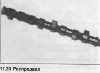
20. Clean the camshaft (photo), check its condition on the cam lobes and on the bearing journals.…


21. Begin assembly by lubricating the hydraulic tappets and installing them in the previously marked positions on the valves.

22. Lubricate the bearing journals on the camshaft, then lower the camshaft into place on the lifters, with the cams for cylinder #1 facing up.

23. Install bearing caps No.2 and 5 (position No.4 is plugged). Install the nuts and tighten them evenly to the torque specified in the Specification. Make sure that the caps are correctly oriented as noted during removal because they are slightly offset.

24. Install bearing caps No.1 and 3, install nuts and tighten evenly to the tightening torque specified in the Specification.


25. Lubricate the lugs and outer rim of the new seal. Position it on the front end of the camshaft and use a socket and mallet to tap it into place until it is level with the cylinder head.

26. Install a new rubber plug and half-round gasket onto the head and front bearing covers, then position the new gasket onto the struts.

27. Install the oil deflector, valve cover and related parts. Tighten the nuts.

28. Install the toothed drive belt as described in Chapter 10.

29. Place the container for the seam and the hanger on the valve cover (if any).

30. Install the air cleaner or fuel injection system components as described in Section 3.

31. If any hydraulic tappet has been replaced, do not start or crank the engine for at least the next thirty minutes. This time is necessary to allow excess oil to flow out of the tappet. If this precaution is not taken, there is a risk of the valve striking the piston.

The original source of the article can be found on the website: AudiManual
The article was checked by auto expert Timur Bazhenov
This article is available at russian, bulgarian, belarusian, ukrainian, serbian, croatian, romanian, polish, slovak, hungarian

Share information:
Previous articles
Audi 80 B3: Engine 4-cylinder
Next articles

Timing Belt and Sprockets — Removal, Check and Installation
Engine — complete disassembly
Auxiliary parts — removal and installation
Engine disassembly — general description
Cylinder head — removal and installation
Cylinder head — overhaul
Flywheel/Drive Disc — Removal, Inspection and Installation
Intermediate shaft — removal, inspection and installation


Similar articles on other Audi car models:
Camshaft Cover — Removal and Installation Audi 100 C3 (1982-1990, diesel)
Hydraulic tappets Audi A4 B5 (1994-2001, petrol)
Electrical diagram of the Motronic control unit, air mass meter,… Audi A6 C5 (1997-2004)
Camshaft Audi A8 D2 (1994-2002)
Camshaft chain drives Audi Q5 Type 8R (2008-2017)
Camshaft housing — design description Audi A2 (1999-2005)
Link to this page in different formats


Visitor comments

No comments yet


How much will 42 + 11 =


80(B4, 1991-1996) 
  • General information
  • User manual
  • Maintenance
  • Troubleshooting
  • Power unit
  • Engine
  • Cooling system
  • Heating and ventilation
  • Petrol injection
  • Diesel fuel system
  • Fuel system
  • Exhaust systems
  • Ignition system
  • Transmission
  • Clutch
  • Car gearbox
  • Chassis
  • Brake system
  • Suspension and steering wheel
  • Body
  • Body and trim
  • Electrical equipment
  • Electrical system
  • Electrical circuits
 
80(B3, 1986-1991) 
  • General information
  • Repair characteristics
  • Maintenance
  • Power unit
  • Gasoline engine
  • Diesel engine
  • Engine lubrication system
  • Fuel system (gasoline)
  • Injection system (gasoline)
  • Fuel system (diesel)
  • Ignition system
  • Cooling system
  • Heater
  • Exhaust system
  • Transmission
  • Clutch and gearbox
  • Chassis
  • Steering
  • Brake system
  • Car suspension
  • Body
  • Body elements
  • Electrical equipment
  • Power devices
  • Lighting and appliances
  • Electrical circuits
 
80(B3, 1986-1991, petrol) 
  • General information
  • User manual
  • Maintenance
  • Power unit
  • Engine 4-cylinder
  • Engine 5-cylinder
  • Cooling system
  • Fuel and exhaust systems
  • Ignition system
  • Transmission
  • Clutch
  • Mechanical transmission
  • Automatic transmission
  • Drive shafts
  • Chassis
  • Brake system
  • Suspension
  • Steering
  • Body
  • Exterior
  • Interior
  • Electrical equipment
  • Equipment and devices
  • Electrical circuits
 
80(B2, 1979-1986) 
  • General information
  • User manual
  • Power unit
  • Engine FZ
  • Engine EP, YP, YZ, DT, DS, DZ
  • Transmission
  • Clutch
  • 4 speed gearbox
  • 5 speed gearbox
  • Front wheel drive
  • Chassis
  • Front suspension
  • Rear suspension
  • Steering
  • Brake system
  • Electrical equipment
  • Equipment and devices
  • Electrical circuits
 
AudiManual.ru © 2017-2026 · Mobile version · Feedback · Sitemap: EN BG BY UA RS HR RO PL SK HU · Site search · News and articles
80 B2 · 80 B3 petrol · 80 B3 · 80 B4 · 100 C3 diesel · 100 C3 petrol · 100 C3 · 100 C4 petrol · 100 C4 · A3 Type 8L · A4 B5 petrol · A4 B5 · A4 B6 petrol · A4 B6 · A4 B7 · A4 B8 · A6 C4 · A6 C5 · A6 C5 Allroad · A8 D2 · Q5 Type 8R · Q7 Typ 4L · Audi A2 ·
This site uses cookies 🍪. Click the button to accept this fact.