
2. Remove the flywheel/drive plate bolts. Temporarily insert the bolt into the cylinder block and use a screwdriver to lock the flywheel, or make a holding tool as shown in Photo 25.79D.
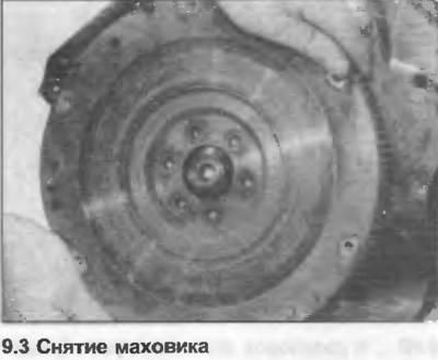
3. Remove the flywheel/drive plate from the crankshaft (photo).
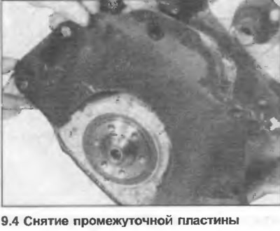
4. Remove the intermediate plate from the pins on the rear of the cylinder block (photo). Note the location of the wiring bracket.
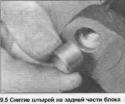
5. If necessary, remove the pins from the block (photo).
6. Unscrew the nuts, remove the fuel container and the suspension from the valve cover (where it is equipped).
7. Unscrew and remove the oil filter.
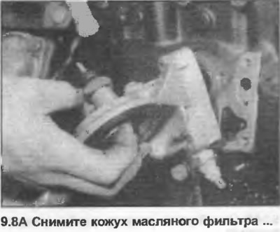
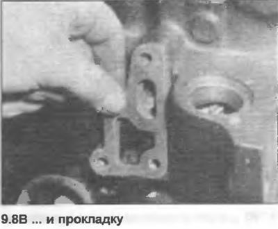
8. Unscrew the oil filter housing from the block, remove the gasket (photo).
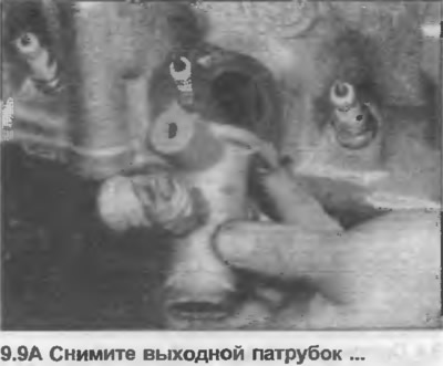
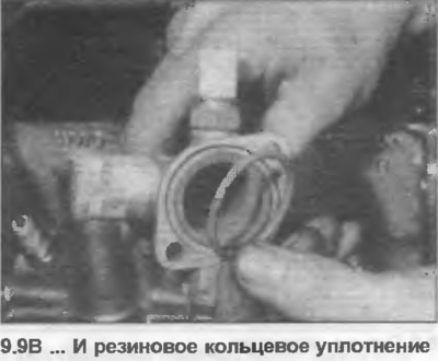
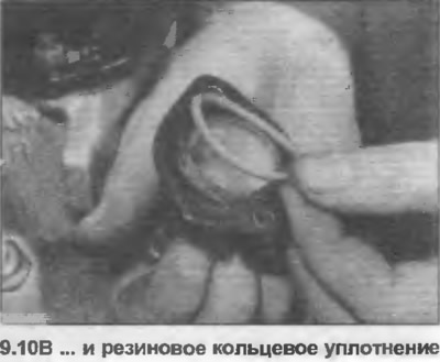
9. Unscrew the outlet pipe from the cylinder head. Remove the rubber O-ring seal at the base of the elbow pipe (photo).
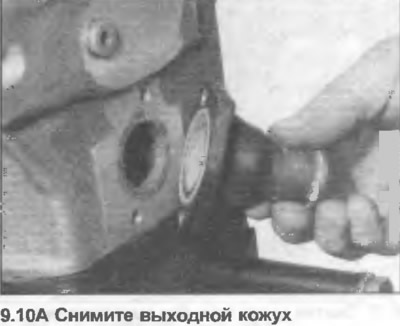
10. Unscrew the outlet housing from the rear of the cylinder head. Remove the rubber O-ring seal at the base of the housing (photo).
11. Unscrew the bolts and remove the pulley from the water pump.
12. Unscrew the nut, remove the special bolt securing the lower cover of the drive to the water pump assembly.
13. Unscrew the water pump assembly from the cylinder block, remove the O-ring.
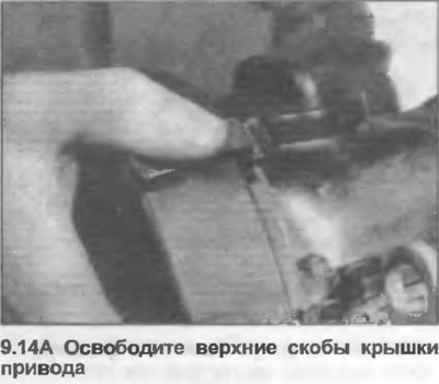
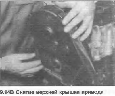
14. Release the staples and (where is it used) unscrew the nut, then remove the top cover of the drive (photo).
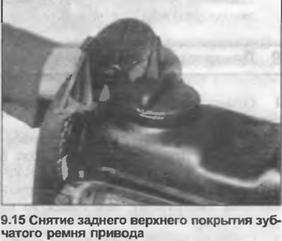
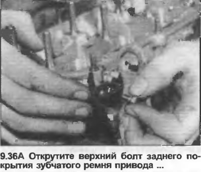
15. Unscrew the nuts, remove the rear upper cover of the timing belt from the valve cover (photo).
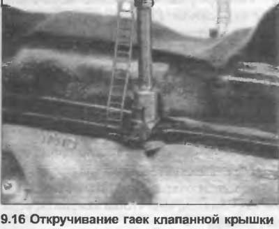
16. Remove the remaining valve cover nuts, noting the location of the wiring harness and ground clamp (photo).
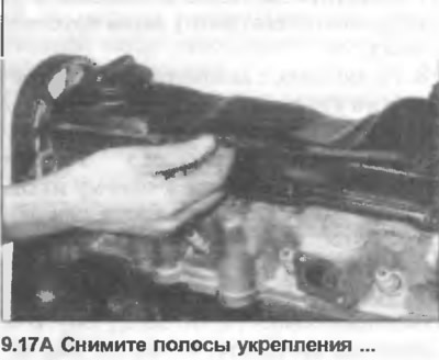
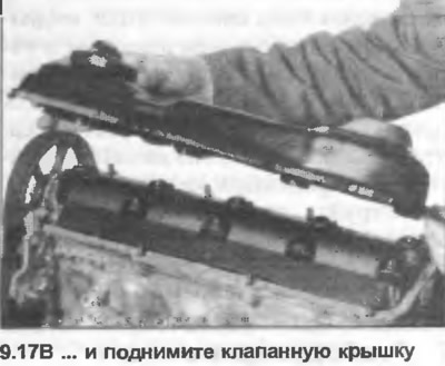
17. Remove the reinforcement strips and lift the valve cover (photo).
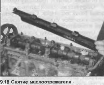
18. Remove the oil deflector (photo).
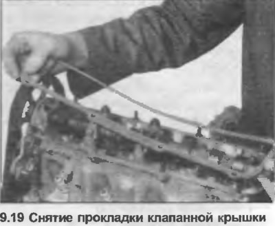
19. Remove the gasket from the struts on the cylinder head (photo).
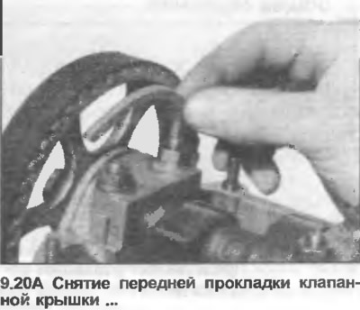
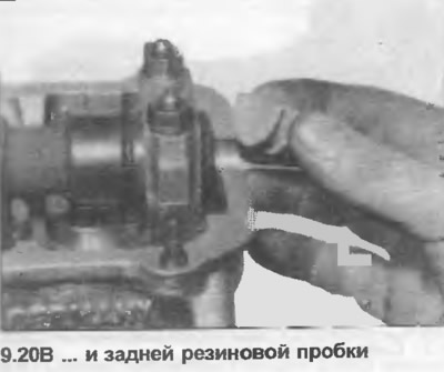
20. Remove the semi-circular gasket from the groove in the front camshaft bearing cover. Also remove the rubber plug on the rear of the cylinder head (photo).
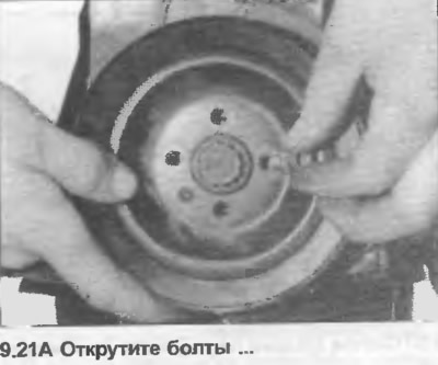
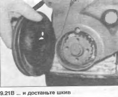
21. Mark the position of the drive belt pulley and crankshaft sprocket relative to each other, then unscrew the bolts securing the drive belt pulley to the crankshaft sprocket. Remove the pulley (photo).
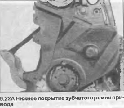
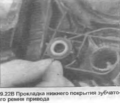
22. Unscrew the bolts, remove the lower cover of the toothed belt drive. For one of the bolts you will need a socket wrench. Remove the special gasket from the top of the cover (photo).
23. Turn the crankshaft clockwise until the mark on the rear of the camshaft sprocket aligns with the top of the cylinder head on the left side.
24. Loosen the nut and turn the tensioner hub counterclockwise to remove tension from the timing belt.
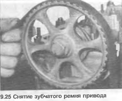
25. Mark the direction of rotation of the timing belt with an arrow, then remove it from the tensioner, camshaft sprocket, intermediate shaft sprocket and crankshaft sprocket (photo).
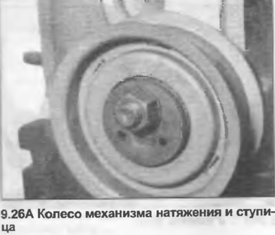
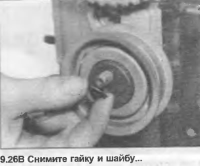
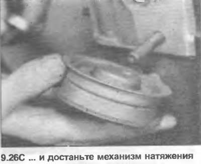
26. Unscrew the nut, remove the washer and remove the tensioner wheel and the screwdriver from the stand on the front side of the cylinder head (photo).
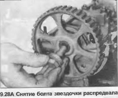
27. Remove the bolt securing the sprocket to the camshaft. A tool can be used to lock the sprocket as shown in photo 25.53, and this should be preferred to inserting the tool through the hole in the sprocket. The latter method can damage the top surface of the cylinder head.
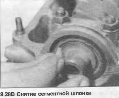
28. Remove the bolt and washer, remove the sprocket from the camshaft. Remove the woodruff key (photo).
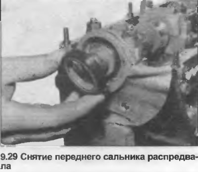
29. Use a screwdriver to pry out the front camshaft oil seal (photo).
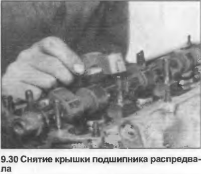
30. Mark the position of the camshaft bearing caps, then evenly unscrew the nuts and remove the caps (photo).
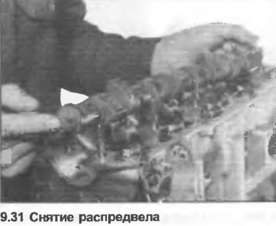
31. Lift the camshaft from the cylinder head (photo).
32. Prepare in advance a box with internal compartments marked with cylinder numbers.
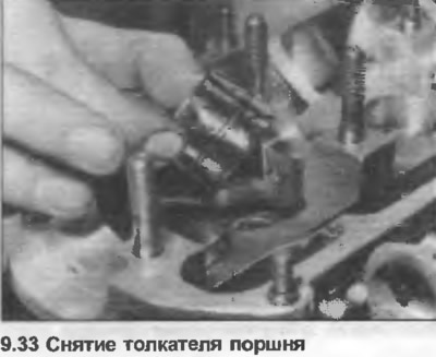
33. Lift the hydraulic lifters (photo). Place the lifters upside down in the box, preventing oil from leaking out.
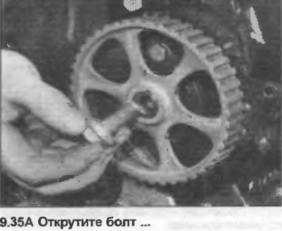
34. Loosen the bolt securing the sprocket to the intermediate shaft, locking the sprocket with the tool shown in photo 25.46.
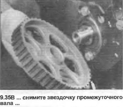
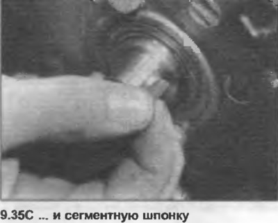
35. Remove the bolt and sprocket from the intermediate shaft. Remove the woodruff key (photo).
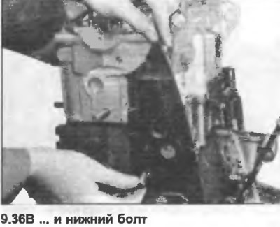
36. Unscrew and remove the rear cover of the toothed drive belt (photo).
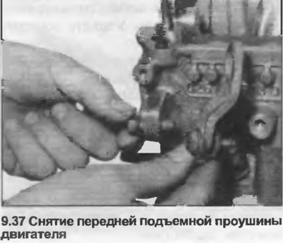
37. Unscrew the front engine lifting eye from the cylinder head (photo).
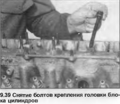
38. Loosen the cylinder head mounting bolts one turn at a time in the reverse order to that shown in Fig. 1.2.
39. Remove the cylinder head mounting bolts together with their washers (photo).
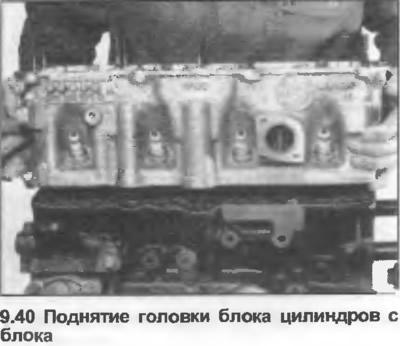
40. With the bolts removed, lift the cylinder head off the block (photo). If it is stuck, hit it with a wooden mallet. Do not pry into the gasket joint.
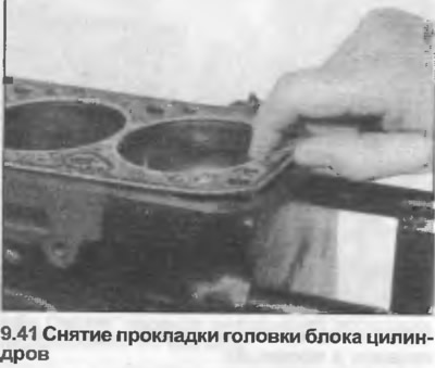
41. Remove the cylinder head gasket from the block (photo).
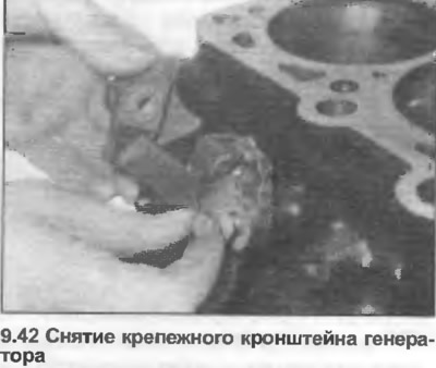
42. Unscrew and remove the generator mounting bracket (photo).
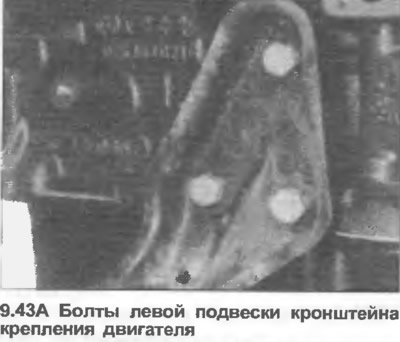
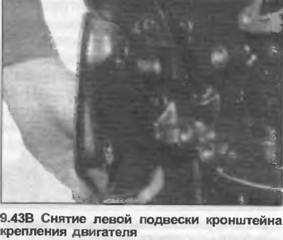
43. Unscrew the engine mounting bracket hanger on the left side of the block (photo).
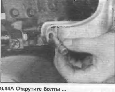
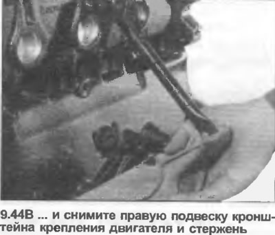
44. Unscrew the engine mount bracket hanger and rod on the right side of the block using a socket wrench (photo).
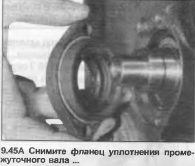
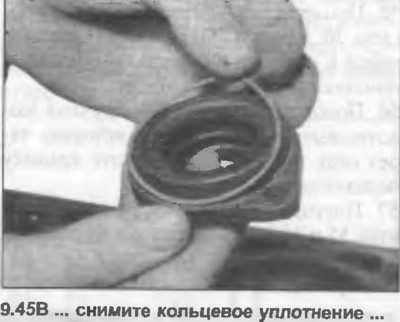
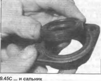
45. Unscrew the two bolts from the intermediate shaft seal flange. Remove the flange, O-ring and oil seal (photo).
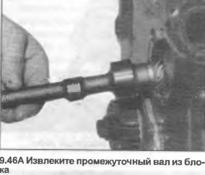
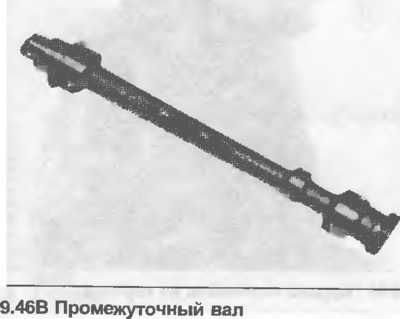
46. Remove the intermediate shaft from the block (photo).
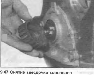
47. Temporarily insert the two flywheel/drive plate bolts into the rear of the crankshaft and use a long rod to block the crankshaft. Remove the crankshaft sprocket bolt (tightly clamped), and remove the sprocket from the crankshaft (photo).
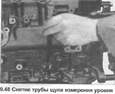
48. Grasp the dipstick tube with a pair of grips and carefully pull it out of the hole in the block (photo).
49. Turn the engine over, then loosen and remove the oil pan bolts.
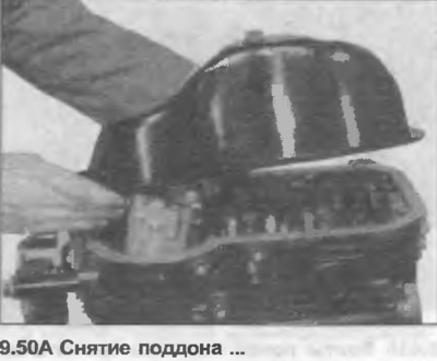
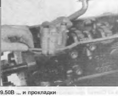
50. Remove the pan and gasket (photo).
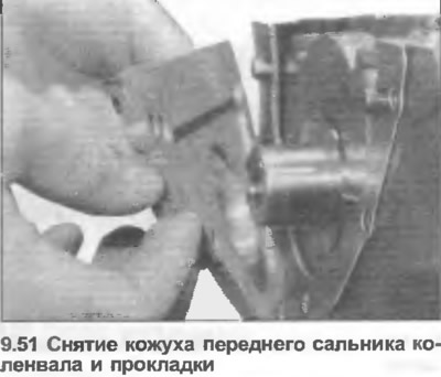
51. Unscrew and remove the front and rear crankshaft oil seal covers, remove the gaskets (photo).
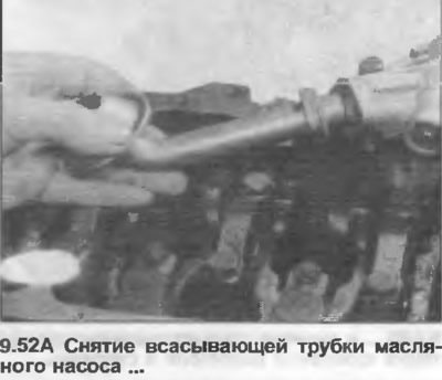
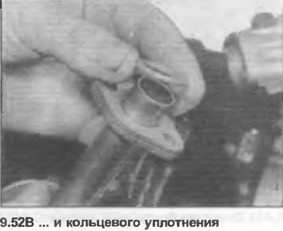
52. Using a socket wrench, unscrew the bolts and remove the suction pipe from the oil pump. Remove the O-ring (photo).
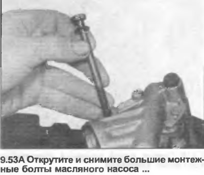
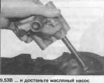
53. Loosen and remove the large oil pump mounting bolts, then remove the pump from the block (photo).
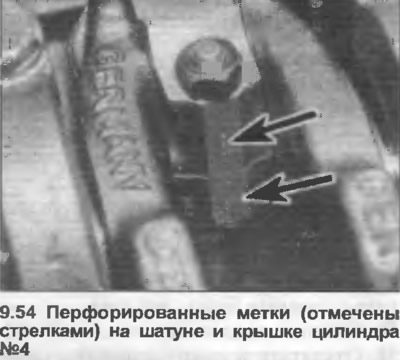
54. Use a punch to mark the position of each connecting rod and cover according to the cylinder number (photo).
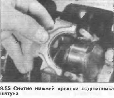
55. Turn the crankshaft so that piston No.1 is at BDC, then unscrew the nuts and remove the lower connecting rod bearing cover (photo).
56. Lay the block on its side and use a hammer handle to push the connecting rod and piston out through the top of the cylinder. Place the bearing cap with the connecting rod.
57. Repeat the procedure given in steps 55 and 56 for the remaining pistons and connecting rods.
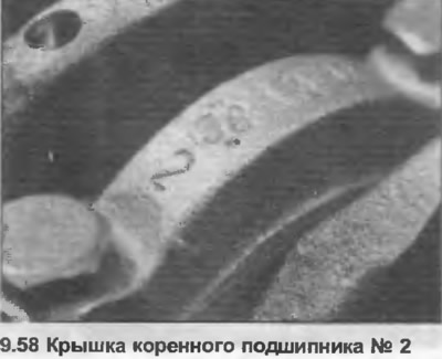
58. Check that each main bearing cap is numbered (photo), starting from the front end of the engine.
59. Loosen and remove cover bolts No.1, 2, 4 and 5, then remove the covers.
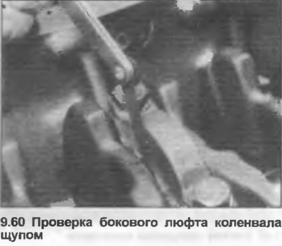
60. With cover #3 installed, determine the crankshaft lateral clearance with a feeler gauge inserted between the thrust washer and the crankshaft bridge (photo). This will allow you to determine the wear of the thrust washers by comparing the lateral clearance with the data in the Specifications.
61. Unscrew and remove main bearing cap No.3.
62. Ensure that each bearing shell is retained with the appropriate cover.
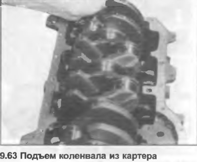
63. Lift the crankshaft out of the crankcase (photo).
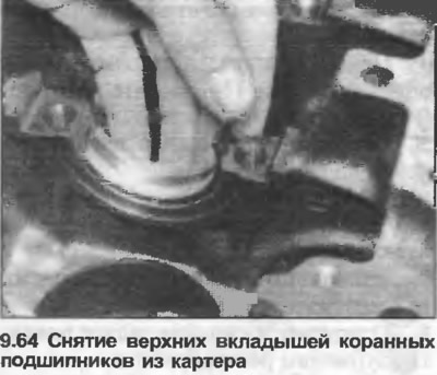
64. Remove the bearing shells from the crankcase, stacking them in the appropriate order (photo).
65. The engine is now completely disassembled.