



Table of contents: Removal the engine with the manual… ↓ Removal the engine without the… ↓ Installation ↓
1. Remove the hood as described in Section 11.
2. Disconnect the negative battery cable.
3. Unscrew and remove the mudguard from under the engine.
4. Place a suitable container under the pan, then remove the drain plug and drain the engine oil. Clean, install and tighten the plug.
5. Drain the cooling system as described in Section 2.
6. Remove the air filter and pipe system, and where equipped, the injection system components, as described in Section 3.
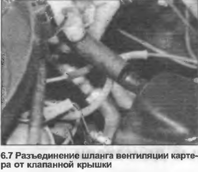
7. Disconnect the crankcase ventilation hose from the valve cover (where is there) (photo).
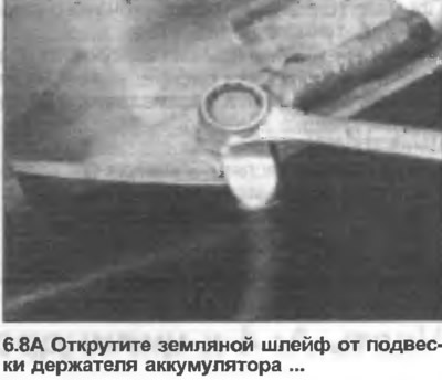
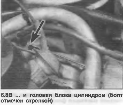
8. Unscrew the ground cable from the battery holder suspension and cylinder head (photo).
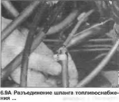
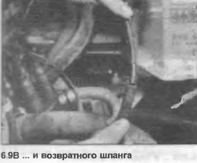
9. Disconnect the fuel supply and return hoses at the bulkhead (photo).
10. Disconnect the accelerator and throttle cables as described in Section 3.
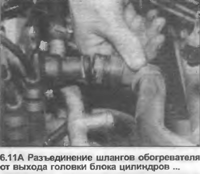
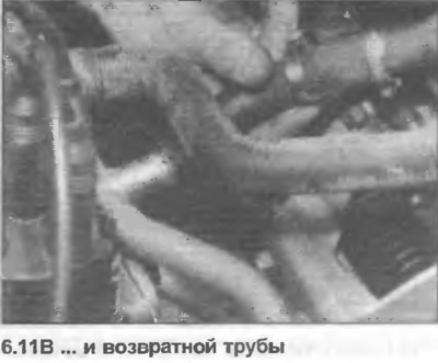
11. Disconnect the heater hoses at the bulkhead, noting their location. Disconnect them from the cylinder head outlet and return pipe and remove (photo).
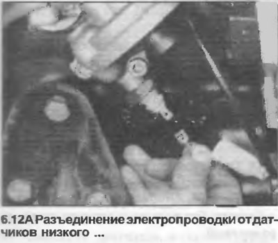
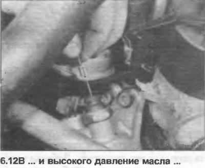
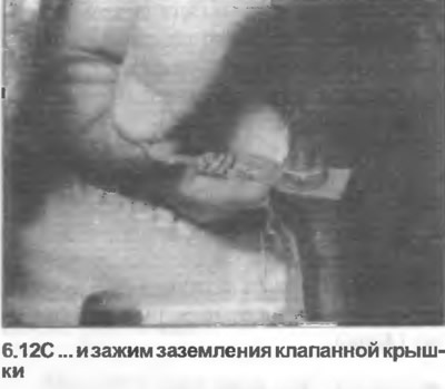
12. Note the direction and location of the engine wiring harness, then disconnect the wires and remove the harness. Below is a list of wires, which may vary depending on the model.
- Coolant temperature sensors
- Ignition coil high voltage wire
- Oil pressure sensors
- Generator
- Gearbox switches and speed sensor
- Oil temperature sensor
- Earth trail from valve cover (photo)
- Starter
- Carburetor or fuel injection system equipment
- Distributor
13. Disconnect the vacuum hoses from the distributor and intake manifold, depending on the model.
14. Remove the radiator as described in Section 2.
15. On models equipped with power steering, remove the pump as described in Section 10, but do not disconnect the hoses, move the pump to the side.
16. On models equipped with air conditioning, remove the compressor as described in Section 11, but do not disconnect the coolant pipes, move the block to the side.
17. Disconnect and remove the lower hose from the water pump.
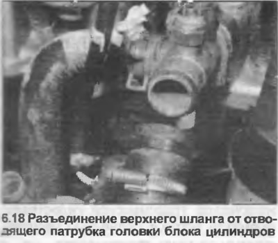
18. Disconnect and remove the upper hose from the outlet pipe on the left side of the cylinder head (photo).
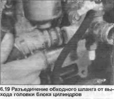
19. If necessary, disconnect the bypass hose from the water pump and the cylinder head outlet pipe (photo).
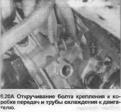
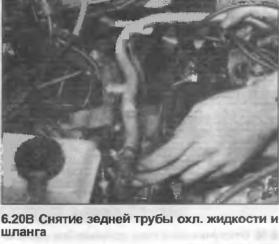
20. Disconnect the hose from the intake manifold by unscrewing the bracket suspension bolt, remove the hose and the coolant pipe at the rear of the engine (photo).
21. If required, the alternator and drive belt can be removed at this stage as described in Section 12.
22. Remove the radiator grille as described in Section 11.
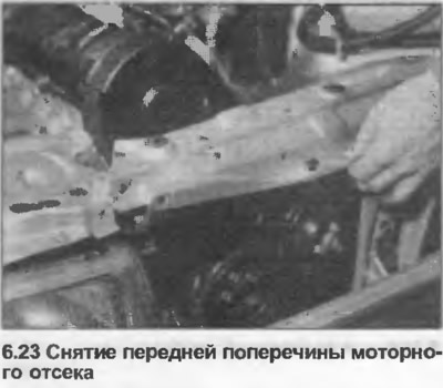
23. Release the hood lock control cable (Section 11), then unscrew and remove the crossbar from the front of the engine compartment (photo).
24. On manual transmission models, remove the clutch slave cylinder as described in Section 5, but do not disconnect the pipe, move the cylinder on the partition
25. Unscrew the nuts securing the exhaust outlet pipe to the exhaust manifold.
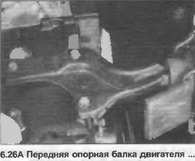
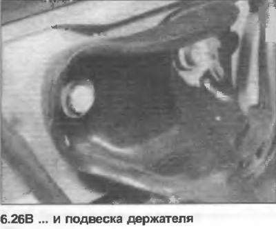
26. Unscrew the front engine support beam from the cylinder block. If necessary, you can also unscrew the holder suspension from the front crossmember (photo).
Removal the engine with the manual transmission attached
27. Apply the parking brake, jack up the front of the vehicle and support it on axle stands.
28. Unbolt the exhaust outlet pipe from the mount on the side of the transmission. For additional work space, it is recommended to remove the complete exhaust system as described in Section 3. If the original system is installed, you will need to unbolt the left rear shock absorber and raise the rear of the car to remove the system. If the repair system is installed, you can increase the gap between the rear axle and the body to make removal easier. If equipped, disconnect the wiring from the catalytic converter.
29. Unscrew the ground cable from the gearbox.
30. Unscrew the nuts, remove the cross member from the bottom behind the gearbox.
31. On models with the Procon-Ten protection system, disconnect the cables from the gearbox as described in Section 7.
32. Loosen the clamp bolt and pull the gear shift sleeve off the gear shift rod.
33. Unscrew and remove the front gearbox cover.
34. Once equipped, unscrew the drive shaft cover under the vehicle.
35. Loosen and remove the bolts securing the inner CV joints of the drive shaft to the gearbox drive flanges. Note the location of the bolt plates, remove the gaskets if any. Tie up the drive shafts and wrap the inner joints with cellophane to prevent dust and dirt from getting in.
36. Lower the vehicle to the ground if necessary, then support the transmission with a jack.
37. Remove the bolt securing the rear support beam to the rubber mount on the rear of the transmission. Loosen the outer bolt and move the rod to the side. You can also completely unscrew the bracket from the transmission.
38. Attach the winch, slightly lift the weight of the engine. The winch must be positioned so that the weight of the gearbox when lifting slightly tilts the engine back.
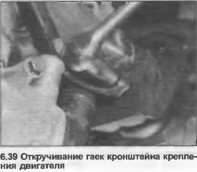
39. Unscrew the nuts from the engine mounting brackets (photo).
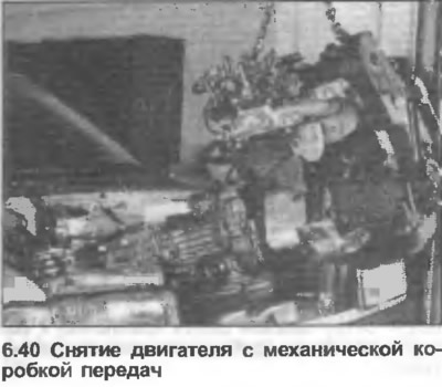
40. Raise the engine off the mounts, move it forward, then lower the jack and lift the engine and transmission out of the engine bay, rotating them as necessary (photo).
41. Lower the engine and gearbox to the floor.
42. If necessary, separate the gearbox from the engine by unscrewing the starter mounting bolts (Section 12), front cover of the gearbox and engine to the gearbox.
Removal the engine without the transmission
43. Apply the parking brake, jack up the front of the vehicle and support it on axle stands.
44. Remove the exhaust outlet pipe (that is, from the front of the exhaust system to the exhaust manifold).
45. Unscrew and remove the front transmission cover.
46. Remove the starter as described in Section 12.
47. On automatic transmission models, remove the bolts securing the torque converter to the drive plate, working through the hole in the front cover. You will need to crank the engine using the starter ring gear on the drive plate, or use a wrench on the bolt on the crankshaft pulley to access each bolt in turn. Use a screwdriver to block the starter ring gear while removing the bolts.
48. On models with automatic transmission, also disconnect the kickdown cable.
49. Loosen and remove the lower bolts securing the transmission to the engine.
50. Lower the front of the car to the ground.
51. Attach the winch, lift the engine slightly. The winch must be placed in the center of the engine.
52. Support the transmission with a jack.
53. Loosen and remove the remaining bolts securing the transmission to the engine, noting the location of the hangers and ground strap.
54. Unscrew the nuts from the engine mounting brackets.
55. Raise the engine off the mounts and place the jack again under the transmission.
56. Separate the engine from the transmission. On models with automatic transmission, make sure that the torque converter remains fully seated in the transmission grooves.
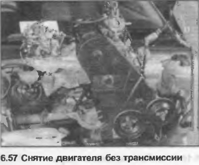
57. Move the engine and lift it out of the engine compartment (photo), then lower it to the floor.
58. On automatic transmission models, ensure that the torque converter remains in its normal position by securing it with a piece of metal strip to one of the mounting bolt holes.
Installation
59. Installation is carried out in the reverse order. But before starting the engine, make sure that it is filled with oil and that the cooling system is filled with coolant. Before squeezing the engine and gearbox installations, rock the engine by hand to ensure proper seating. Make sure that the starter wiring does not touch the engine or mounting brackets. Adjust the accelerator and throttle cables as described in Section 3.