2. Unscrew the nuts, remove the end of the support plate (where is there).
3. Remove the screws, take out the small end cap and gasket, remove the snap ring, remove the gaskets. Note the exact number of gaskets, as they determine the shaft play.
4. Unscrew the tie bolts and remove the bearing housing.
5. Unscrew the nut, disconnect the wire in the traction relay
6. Note the position of the brush holder plate, remove the plate from the excitation winding casing and armature.
7. Unscrew the three bolts, remove the traction relay from the casing on the drive side. Disconnect the traction relay from the control lever.
8. Remove the control lever covers from the drive side housing.
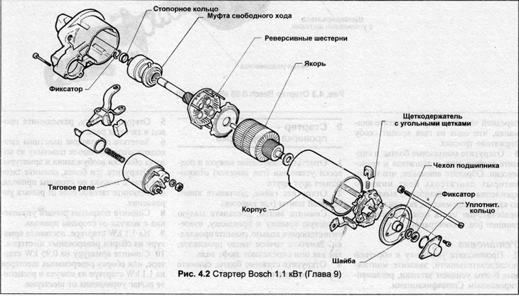
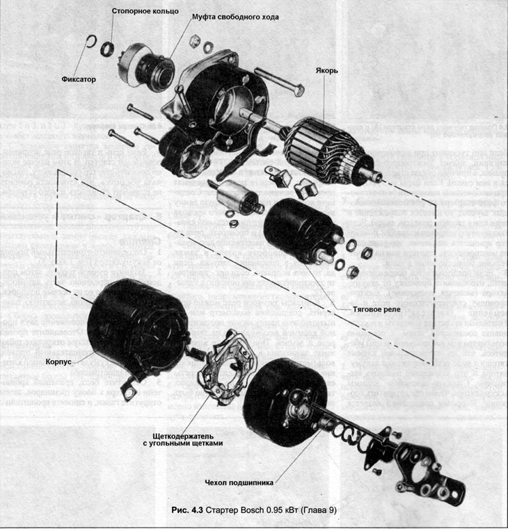
9. On the 1.1 kW starter, remove the fittings from the reverse gear assembly.
10. Remove the armature on the 0.95 kW starter, or the reversing gear assembly on the 1.1 kW starter from the housing and disengage the control lever from the gear.
11. Move the thrust ring away from the retaining ring, remove the retaining ring, and remove the thrust ring.
12. Remove the drive gear from the reversing mechanism or fittings.
13. Clean all components, wipe dry, check their condition. Check the teeth of the drive gear, the correct operation of the freewheel clutch, which should rotate only in one direction. If the shaft bushings are worn, they can be removed with a soft metal drift and new bushings installed. New bushings should be soaked in hot oil for about five minutes. Clean the commutator with a rag. Small irregularities can be removed with sandpaper. On a 1.1 kW starter, it is better not to disassemble the reversing mechanism assembly, but to replace it entirely if it makes noise during operation.
14. Measure the length of the brushes. If the length is less than the data in the Specifications, replace the brush holder plate. To do this on a 0.95 kW starter, unsolder the copper braid following the brush holder and solder it to the new holder.
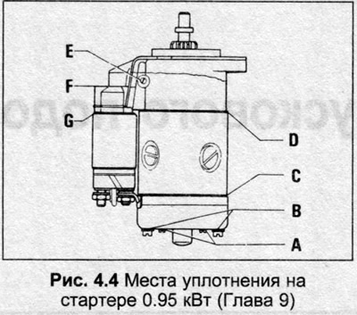
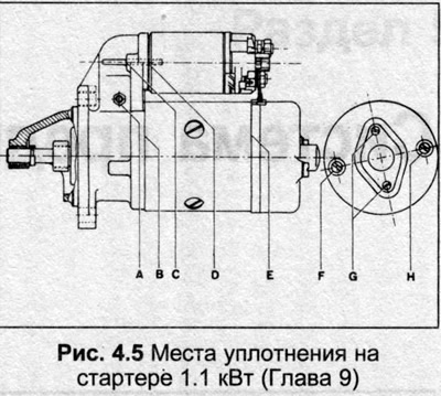
15. Assembly is carried out in the reverse order. Place a new retaining ring on the end of the shaft, the groove for the retaining ring must not be damaged. Scores on the edges of the groove must be removed with a fine file. When assembling, apply sealant to the places shown in Fig. 4.4 and 4.5.