
Table of contents: Removal ↓ Disassembly ↓ Inspection and defect detection of… ↓ Assembly ↓ Installation ↓ Adjusting the clutch pedal free… ↓
Hydraulically operated clutch
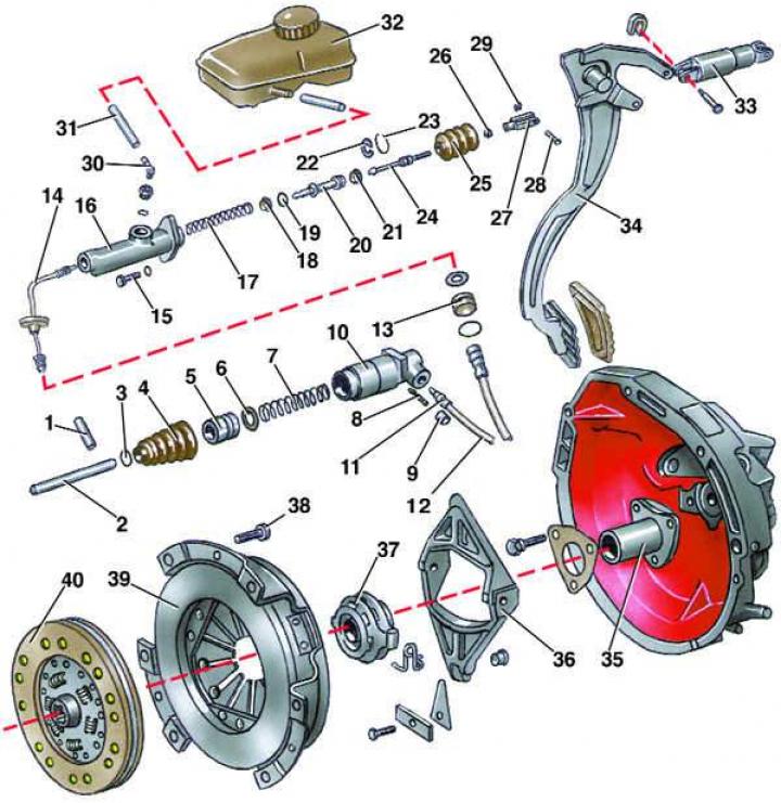
- 1 - locking pin;
- 2 - pusher;
- 3 - retaining ring;
- 4 - mudguard;
- 5 - piston;
- 6 - working cylinder cuff;
- 7 - spring;
- 8 - bleed valve;
- 9 - protective cap;
- 10 - working cylinder body;
- 11 - nipple;
- 12 - hose;
- 13 - coupling sleeve;
- 14 - tube;
- 15 - bolt;
- 16 - cylinder body;
- 17 - return spring;
- 18, 21 - cuffs;
- 19 - bypass ring;
- 20 - piston;
- 22 - locking bracket;
- 23 - retaining ring;
- 24 - pusher;
- 25 - mudguard;
- 26 - lock nut;
- 27 - Pusher fork;
- 28 - finger;
- 29 - retaining ring;
- 30 - nipple;
- 31 - working fluid supply pipe;
- 32 - tank;
- 33 - return spring;
- 34 - clutch pedal;
- 35 - guide bushing;
- 36 - clutch release fork;
- 37 - clutch release bearing;
- 38 - bolt;
- 39 - pressure plate assembly;
- 40 - driven disk
Removal
1. Disconnect the wire from the negative terminal of the battery.
2. Disconnect the working fluid supply pipe from the master cylinder and plug the opening in the pipe.
3. Remove the lower left instrument panel trim to gain access to the master cylinder mount.
4. Disconnect the tube from the end of the master cylinder by unscrewing the fastening nut and plug the tube hole.
5. Disconnect the push rod fork from the clutch pedal by removing the retaining ring and removing the pin.
6. Loosen the two mounting bolts and remove the master cylinder from the vehicle.
Disassembly
1. Clean the master cylinder from dirt.
2. Remove the mudguard from the master cylinder body.
3. Remove the retaining ring and remove the pusher from the housing.
4. Push the piston out of the cylinder body through the end hole using a suitable rod until it appears from the cylinder. Finally remove the piston from the cylinder body together with the return spring.
5. Remove the spring from the piston and cuff.
Inspection and defect detection of master cylinder parts
1. Wash the master cylinder parts with clean brake fluid and dry.
2. The mirror of the main cylinder should not have any scratches, cavities or corrosion spots. If these defects are present, the cylinder must be replaced. There should be no mechanical damage on the threaded parts of the cylinder.
3. The master cylinder seals must be elastic and flexible. Torn, swollen and hardened seals, as well as those with scratches on the working surfaces, must be replaced.
4. The end of the pusher and the mating surface of the piston should not have any obvious signs of one-sided wear. The surfaces of the piston that contact the cylinder mirror should also not have any signs of one-sided wear. Otherwise, it is recommended to replace the pusher and piston. The piston valve should not have any visible signs of deformation and should fit tightly to the end of the piston.
5. The master cylinder mudguard must not have any cracks or through holes. It must be installed on the pushrod and the master cylinder body with a slight tension. Otherwise, replace the mudguard.
6. The spring must have elastic properties. Breakage of the spring is not allowed.
7. The threads of the tube and hose tips must not have any mechanical damage. The nozzles of the tips must not have any cracks or traces of visible deformation.
Assembly
1. Lubricate the cuff with clean brake fluid and install it on the spring, orienting the working edge towards the spring.
2. Carefully insert the spring into the cylinder body.
3. Lubricate the cuff with clean brake fluid and install it on the piston, orienting the working edge towards the spring.
4. Insert the piston with the bypass ring placed on it into the cylinder body.
5. Install the locking bracket onto the pushrod if it was removed.
6. Insert the push rod into the cylinder body and install the retaining ring.
7. Install the mudguard onto the cylinder body.
Installation
Install the clutch master cylinder in the reverse order. Tighten the master cylinder mounting bolts to 20 N·m (2.0 kgf·m). After installation, bleed the clutch hydraulic drive (see subsection 7.3.4).
Adjusting the clutch pedal free travel
1. Loosen the pushrod fork lock nut.
2. By unscrewing or screwing the pusher by hand or with pliers, achieve a position of the clutch pedal relative to the brake pedal of 10 mm.
3. Tighten the lock nut.
The original article is located on the online resource Audimanual.ru