
Table of contents: Definition of the correction "r" ↓ Adjusting the distance between the… ↓
The distance between the end face of the drive gear and the differential axis is defined as the difference between the calculated value "Ro" of this distance, which is constant and equal to 59.65 mm, and the variable correction "r", which is the deviation of the drive gear from the nominal position. The correction value "r" is rolled only for the main pair supplied as spare parts. It is marked in hundredths of a millimeter on the driven gear, always with a plus sign.
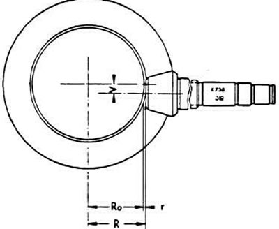
Ro - calculated distance between the end of the drive gear and the differential axis, equal to 59.65 mm; r - variable correction to the nominal position of the drive gear; R - actual distance between the end of the drive gear and the differential axis
Adjustment of the distance between the end of the drive gear and the differential axle is achieved by selecting the thickness of the adjusting ring "S3" (see diagram), installed behind the flange of the outer wheel of the front tapered roller bearing of the secondary shaft, and the adjusting ring "S4", installed between the rear cover of the crankcase and the outer ring of the rear tapered roller bearing of the secondary shaft.
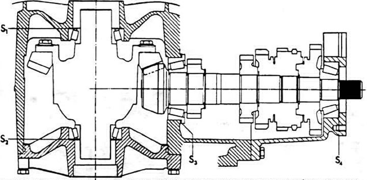
Scheme for adjusting the distance between the end of the drive gear and the differential axis and the lateral clearance in the engagement of the main gear gears: S1 and S2 - adjusting rings for lateral clearance in the engagement of the main transmission gears; S3 and S4 - adjusting rings for the distance between the end of the drive gear and the differential axis
Note: The distance between the end of the drive pinion and the differential axle must be adjusted again when replacing the driven pinion of the main gear and the secondary shaft. In case of replacing other parts that affect the position of the drive pinion (and, therefore, the secondary shaft), perform the adjustment based on the measurement of the installation position of the secondary shaft, made before disassembling the gearbox.
Definition of the correction "r"
The determination of the correction "r" is made if its value is not marked on the driven gear and if it is necessary to replace parts that directly affect the position of the driving gear of the main transmission (both tapered roller bearings, secondary shaft, gearbox housing). The work is carried out before removing the gearbox.
Remove the differential as described above.
Set up and equip the VW 385/1 measuring mandrel as described below in the paragraph "Adjusting the distance between the end of the pinion and the differential axle".
Measure the correction value "r", which is, for example, 0.18 mm. After replacing the parts, adjust the position of the drive gear as shown below. When determining the thickness of the adjusting ring "S3", take into account the measured correction value "r".
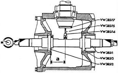
Scheme for measuring the value of the correction "r"
Adjusting the distance between the end of the drive gear and the differential axle
Install the adjustment ring "Sj" with the calculated total thickness (in our example "Sob" 1.60 mm) under the outer ring of the rear tapered roller bearing of the secondary shaft.
Install the rear cover of the gearbox housing.
Turn the secondary shaft several times in both directions
Adjust the adjusting ring of the VW 385/1 measuring mandrel to dimension "a" (see diagram), equal to 50 mm.
Attach the indicator with a 9.3 mm extension to the measuring mandrel (vW 365/27 fixture).
Install the VW 385/27 adjusting gauge, which provides a calculated distance between the end of the pinion and the differential axis "Ro" equal to 59.65 mm, on the measuring mandrel and set the indicator to the zero position with a preliminary leg tension equal to 1 mm.
Move the movable adjustment ring until it stops.
Install the VW.385/17 adjusting plate onto the pinion head.
Remove the adjusting gauge and insert the measuring mandrel into the gearbox housing, pointing the VW 385/2 washer towards the differential bearing cover.
Install the differential bearing cover and press it down, tightening the four mounting bolts.
Pull the second adjusting washer back as far as possible using the sliding adjustment ring so that the measuring mandrel can be turned manually.
Turn the measuring mandrel so that the indicator leg rests against the measuring plate installed on the head of the drive gear, and the indicator arrow deflects as much as possible (to the starting point of movement 8 in the opposite direction). Let the value "r1" measured in this way be 0.46 mm.
Calculate the thickness of the adjusting ring "S3" using the formula
S3 = r1 + r
where
r1 - measured value by the maximum deviation of the indicator arrow;
r - the value of the correction to the nominal position of the main transmission drive gear.
Example "r1" is 0.46 mm; "r" — 0.18 mm.
S3 = 0.46 + 0.18 = 0.64 mm
Since the tolerance limits of the thickness of the adjusting rings are known, the calculated | thickness of the adjusting ring "S3" can be selected accurately in all cases.
Calculate the thickness of the adjustment ring "S4" using the formula:
S4 = So6 - S3
Example: So6 is 1.60 mm.
S4 = 1.60 - 0.46 = 0.96 mm
Measure the thickness of the adjusting rings at several points with a micrometer. Make sure that they are free of burrs and other defects. Install only good quality rings.
Checking the adjustment of the distance between the end of the drive gear and the differential axle
Install the secondary shaft, press in the outer bearing rings, installing the selected adjusting rings "S3" and "S4". Turn the secondary shaft in both directions.
Install the universal measuring mandrel and take control measurements.
When the adjustment rings are selected correctly, the indicator should show the correction value "r" with a deviation of ±0.04 mm.
(The article was copied from the website AUDIMANUAL.ru)