



Table of contents: Principle of regulation ↓ Determining the value of the… ↓ Selecting the secondary shaft rear… ↓
Principle of regulation
The distance between the differential axis and the end of the drive gear determines the location of the contact patch in the engagement of the main gear gears. When installing the secondary shaft in the gearbox, this distance affects the degree of wear and noise of the main gear gears. Therefore, it must be adjusted with particular care using a special tool.
The initial value for adjustment is the calculated value of the distance between the differential axis and the end of the drive gear (dimension "R0", see diagram), adjusted by the correction "r", determined during the manufacture of the drive gear. The adjustment consists of placing the adjusting ring S₃ of the required thickness under the outer ring of the rear bearing of the secondary shaft to shift the drive gear in the gearbox housing.
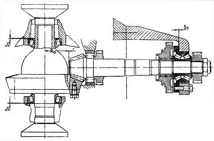
Adjustment and purpose of the distance between the end face of the main gear pinion and the differential axis and the lateral clearance between the teeth of the main gear pinions:
R0 — the calculated distance between the end of the drive gear and the differential axis;
r — measured or marked on the crown of the driven gear correction to the calculated distance between the end of the driven gear of the main transmission and the differential axis;
S₁ — adjusting ring of the distance between the end of the drive gear and the differential axis;
S₂ and S₃ — differential bearing preload adjusting ring.
Determining the value of the correction "r"
Note. This measurement is taken if the driven gear of the main transmission does not have the correction marking "r" in hundredths of a millimeter from the nominal position of the driving gear, and also if there has been a replacement of parts that directly affect the position of the driving gear of the main transmission: the rear double-row tapered roller bearing of the secondary shaft, the crankcase or rear cover of the gearbox, the bearing of the 1st gear gear.
Remove the rear gearbox cover.
Install a special adjusting washer VW 381/11 and secure it strictly at a right angle relative to the secondary shaft, tightening two M8x50 bolts by hand.
Tighten the bolts to 200 Ncm using a torque wrench.
The pinion gear, after tightening the bolts, assumes the position it was in when the rear cover of the gearbox was installed. This operation must be carried out very carefully every time the distance between the end of the pinion gear and the differential axle is adjusted.
Remove the differential.
Install the VW 385 measuring mandrel with the VW 385-30 indicator with a 2 mm foot preload. Set the indicator to "zero".
Determine the calculated value of the size "r", which is the deviation from the size "R0".
When replacing parts, select the thickness of the adjusting ring to achieve maximum possible accuracy in maintaining the obtained size "r".
Selecting the secondary shaft rear bearing adjusting ring
If the final drive is to be used again, press the outer race of the rear bearing together with the old adjusting ring into the gearbox housing. In case of replacement of parts, install the outer race of the bearing without the adjusting ring.
Install the secondary shaft and press on the second inner ring of the rear bearing, as well as the 5th gear.
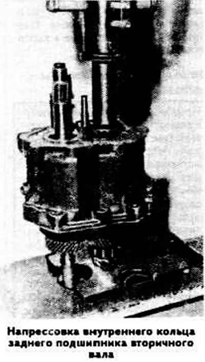
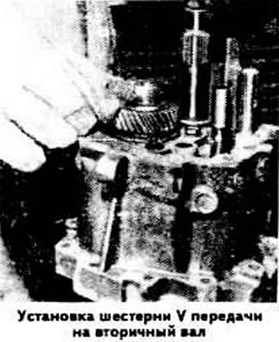
Attach the gearbox housing to the clutch housing, installing a new gasket.
Tighten the secondary shaft rear end nut to a torque of 10.0 kgf·m.
Install the special secondary hall preload mounting bracket VW 381/11 as described above.
Install the VW 385 measuring reference with the VW 385-30 indicator with a 2 mm foot preload. Set the indicator to "zero". Measure the value "r" and compare it with the calculated value "r" if the main gear was replaced, or with the value marked on the driven gear if the main gear was replaced. If the obtained value "r" is less than the calculated one, then an adjusting ring S₃ of greater thickness should be installed, and vice versa. The difference between the obtained and calculated values "r" shows how much the thickness of the adjusting ring S₃ should be reduced or increased.
Remove the measuring instrument kit and install the selected adjusting ring S₃ under the outer ring of the secondary shaft rear bearing.
Install the secondary shaft.
Preload of differential bearings and adjustment of lateral clearance between the teeth of the main gear.
These operations are carried out as described for the CP type 014, see section "Four-speed gearbox".