
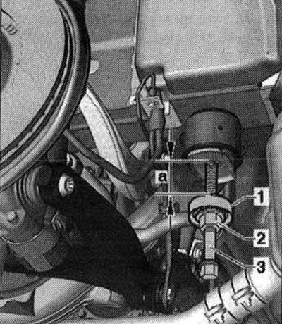
- 1. Mounting device "3301"
- 2. Nut "3346/3"
- 3. Lead screw "3346/2"
Screw the nut "3346/3" onto the lead screw "3346/2" so that the dimension "a" is 4 cm. Lower the subframe only by 4 cm. Install the tools on the subframe as shown in the figure.
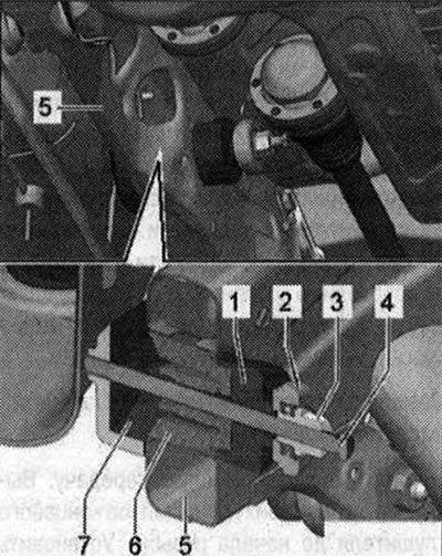
- 1. Pipe "T40185/1". Side "A" should face the subframe.
- 2. Thrust bearing "3301"
- 3. Nut "3346/3"
- 4. Lead screw "T40185/9"
- 5. Subframe
- 6. Silent block
- 7. Pipe "T40185/7". The "open" side faces up
Remove the support from the subframe, while turning the nut "3346/3" and holding the spindle "T40185/9".
Installation
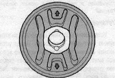
Installation in reverse order. In this case, it is necessary to take into account the mounting position of the silent blocks. The arrows on the back of the silent block must be directed vertically up or down.
Install the tools and silent block on the subframe as shown in the figure.
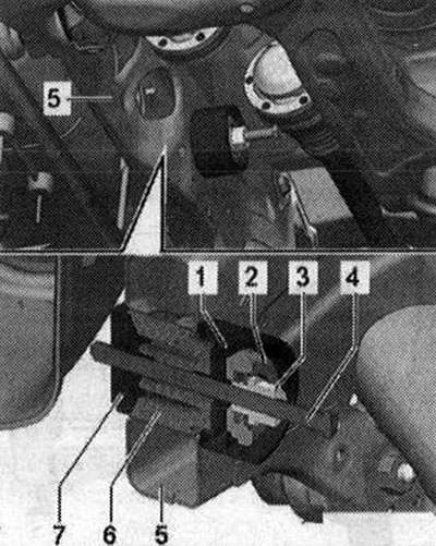
- 1. Pipe "T40185/2". Side "B" should face the subframe.
- 2. Thrust bearing "3301"
- 3. Nut "3346/3"
- 4. Lead screw "T40185/9"
- 5. Subframe
- 6. Silent block
- 7. Thrust washer "T40185/8"
Insert the support into the subframe, while turning the nut "3346/3" and holding the spindle "T40185/9". If after replacing the silent blocks there is damage to the varnished surface of the subframe, it must be repaired using an anti-corrosion coating, primer and black paint.
The original publication in its entirety is posted on the website: AudiManual.ru