
Table of contents: Replacing the front silent block or… ↓ All ↓ Installation position of the front… ↓ Rear hydraulic silent block ↓ Mounting position of the rear… ↓
If a silent block is damaged, the silent block on the opposite side should also be replaced. Before replacing a faulty silent block, the remaining silent blocks should also be checked. If there are cracks, oil leaks or other damage, the silent blocks should be replaced. The serial kit included 2 different silent block designs: a traditional silent block and a hydraulic silent block. Install the car on a lift. Remove the wheels. Remove the coil springs. To replace the silent block, lower the subframe in the front or rear area. It is not necessary to remove the subframe. Lower the subframe alternately in the front or rear area. This will avoid adjusting the wheel alignment angles. The subframe should not be lowered more than 4 cm. Before removing the silent blocks, mark their installation position relative to the subframe.
Replacing the front silent block or hydraulic silent block
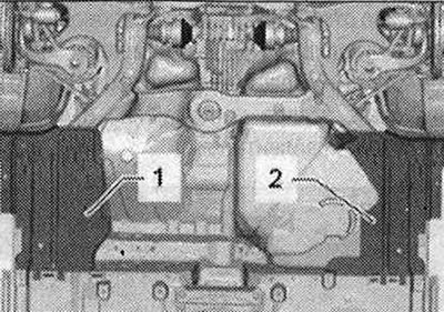
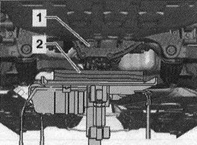
Remove the cover "1" and "2". Remove the fairings from the wheels.
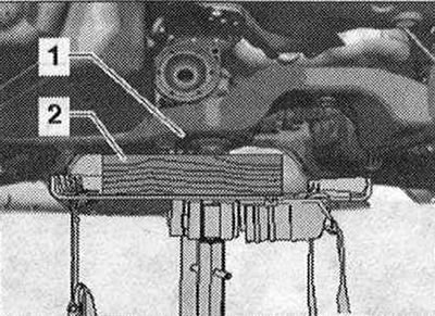
Install a powertrain lift with a universal gearbox grip "V.A.G 1359/2" under the subframe "1". Place a suitable block "2" under the subframe "1".
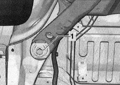
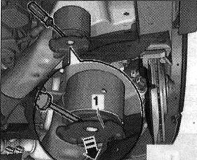
Unscrew bolt "1" on the left and right.
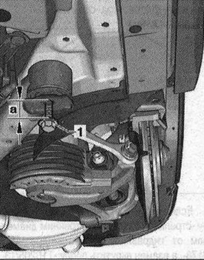
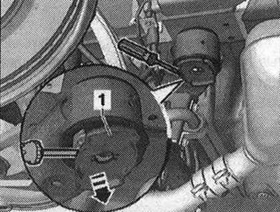
Screw the previously removed bolt "1" into the body, as shown in the figure, on the opposite side from the silent block to be replaced. Screw in bolt "1" so that the distance "a" is 4 cm.
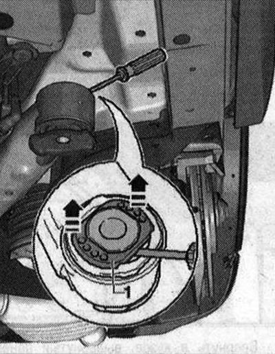
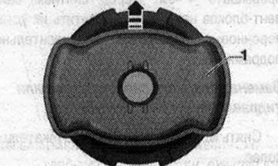
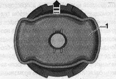
Lower the subframe only by 4 cm. Carefully loosen the anti-rotation protection "1" with a suitable tool, e.g. a screwdriver, in the area of the mounting projections in several stages, alternately on each side of the silent block.
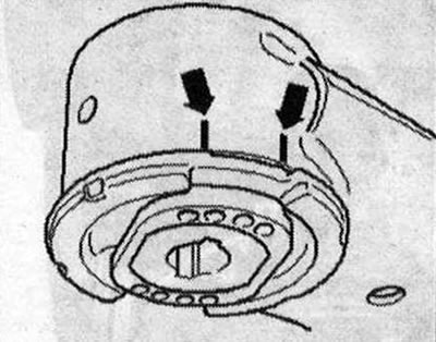
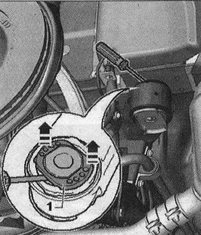
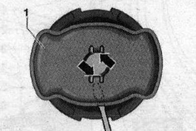
For hydraulic silent block: Pull up plastic insert "1" as shown in the figure.
All
Mark the mounting position of the silent block or hydraulic silent block relative to the subframe, for example, using a felt-tip pen "arrows".
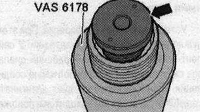
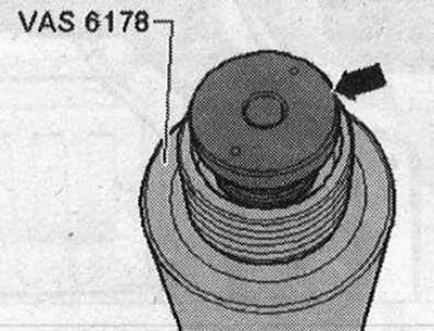
If necessary, unscrew the "arrow" support with the "small" inner diameter from the "VAS 6178" hydraulic cylinder and screw in the "T10205/13" support instead.
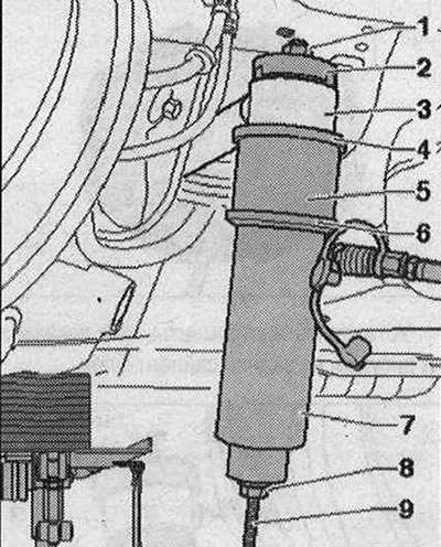
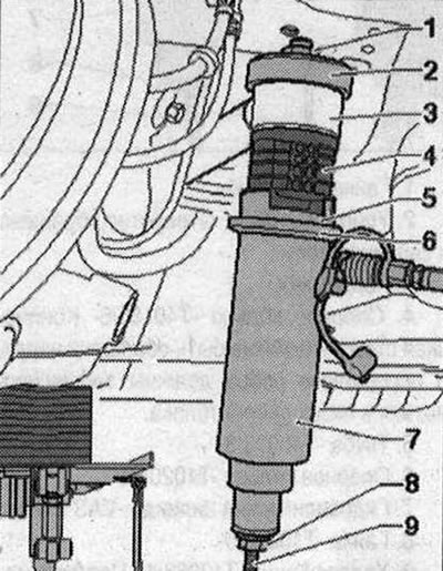
Install the tools as shown in the figure on the front silent block.
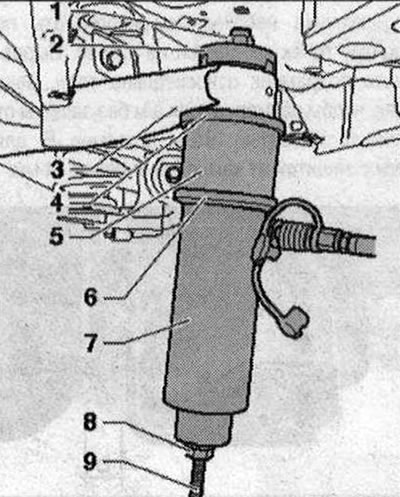
- 1. Nut "T10263/5"
- 2. Stop "T40185/5". The hole faces the silent block
- 3. Subframe
- 4. Support ring "T40185/6" The conical side should be facing up and the jumpers should enter the holes of the silent block
- 5. Pipe "T40033/3"
- 6. Support ring "T10205/4"
- 7. Hydraulic cylinder "VAS 6178"
- 8. Nut "T10263/5"
- 9. Lead screw "T10263/4". The journal of the lead screw faces downwards
Attention! During pressing out, hold the hydraulic cylinder "VAS 6178". The silent block is disconnected by a "jerk". Falling tools and silent block may cause injuries!
Installation position of the front silent block
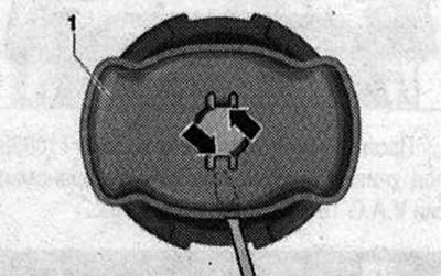
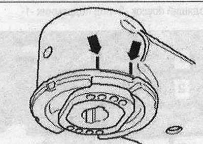
Anti-rotation protection (aluminum plate) "1" is installed perpendicular to the direction of travel. "Arrow" indicates the direction of travel of the vehicle.
Before installing the front silent block, carefully loosen the anti-rotation protection "1" with a suitable tool, e.g. a screwdriver, in the area of the fastening protrusions "arrows" in several stages alternately on each side of the silent block.
Install the tools as shown in the figure on the front silent block.
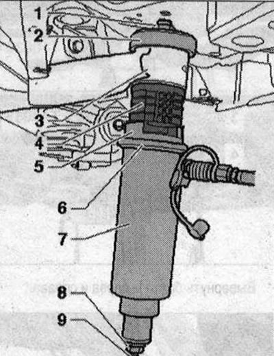
- 1. Nut "T10263/5"
- 2. Stop "T40185/4"
- 3. Subframe
- 4. Silent block or hydraulic silent block
- 5. Stop "T40185/3"
- 6. Support ring "T10205/4"
- 7. Hydraulic cylinder "VAS 6178"
- 8. Nut "T10263/5"
- 9. Lead screw "T10263/4". The journal of the lead screw faces downwards.
Align the silent block according to the applied marks and press it in the correct position so that the flange fits against the subframe bushing "without a gap". To do this, if necessary, press out and press in using a cylinder. Make sure that the silent block does not skew at the beginning of pressing, otherwise the outer ring may be damaged! The ends of the rubber protrusions on the silent block must match the previously applied "arrows" marks on the subframe. After replacing the silent blocks, eliminate possible damage to the paintwork of the subframe using an anti-corrosion coating, primer and black paint. Install the anti-rotation protection on the silent block. Install in the reverse order.
Rear hydraulic silent block
Unscrew the nuts of both brackets of the end muffler to the beginning of the thread. Install a power unit lift with a universal grip for the gearbox "V.A.G 1359/2" under the subframe. Place a suitable block "2" under the subframe "1".
Unscrew the rear subframe bolts. Screw the lead screw "3346/2" with the mounting device "3301" and the nut "3346/3" into the body, as shown in the figure, on the opposite side of the silent block being replaced by a size of approx. 1.5 cm.

- 1. Mounting device "3301"
- 2. Nut "3346/3"
- 3. Lead screw "3346/2"
Screw the nut "3346/3" onto the lead screw "3346/2" so that the dimension "a" is 4 cm. Lower the subframe only by 4 cm. Carefully press the lock against rotation "1" with a suitable tool, for example, a screwdriver, in the area of the protrusions in several stages alternately on each side of the hydraulic silent block.
Pull out the plastic insert "1" upwards as shown in the figure.
Mark the mounting position of the hydraulic silent block relative to the subframe, for example, using a felt-tip pen "arrows".
If necessary, unscrew the "arrow" support with the "small" inner diameter from the "VAS 6178" hydraulic cylinder and screw in the "T10205/13" support instead.
Install the tools as shown in the figure on the rear silent block.
- 1. Nut "T10263/5"
- 2. Stop "T40185/5". The hole faces the silent block.
- 3. Subframe
- 4. Support ring "T40185/6" The conical side should face up, and the transverse ribs should be fixed in the grooves of the silent block.
- 5. Pipe "T40033/3"
- 6. Support ring "T10205/4"
- 7. Hydraulic cylinder "VAS 6178"
- 8. Nut "T10263/5"
- 9. Lead screw "T10263/4". The journal of the lead screw faces downwards.
Attention! During pressing out hold the hydraulic cylinder "VAS 6178". The hydraulic silent block is disconnected with a "jerk".
Falling tools and hydraulic silent block may cause injury!
Mounting position of the rear hydraulic silent block
Anti-rotation protection (aluminum plate) "1" is installed perpendicular to the direction of travel. "Arrow" indicates the direction of travel of the vehicle.
Before installing the rear hydraulic silent block, carefully press the locking device "1" with a suitable tool, such as a screwdriver, in the area of the "arrow" protrusions in several stages alternately on each side of the hydraulic silent block.
Install the tools as shown in the figure on the rear silent block.
- 1. Nut "T10263/5"
- 2. Stop "T40185/4"
- 3. Subframe
- 4. Hydraulic silent block
- 5. Stop "T40185/3"
- 6. Support ring "T10205/4"
- 7. Hydraulic cylinder "VAS 6178"
- 8. Nut "T10263/5"
- 9. Lead screw "T10263/4". The journal of the lead screw faces downwards.
Align the hydraulic silent block according to the applied marks and press it in so that the flange fits against the subframe bushing "without a gap". To do this, if necessary, press it out and press it in further using a cylinder. Make sure that the hydraulic silent block does not skew at the beginning of installation, otherwise the outer ring may be damaged. The ends of the rubber protrusions on the silent block must match the previously applied "arrows" marks on the subframe. After replacing the silent blocks, eliminate possible damage to the paintwork of the subframe using an anti-corrosion coating, primer and black paint. Install the anti-rotation protection on the hydraulic silent block. Install in the reverse order.
Text provided by the online resource Audimanual.ru