
Replacing the front silent block
Remove cover -1 - and -2-. Remove the fairings from the wheels.
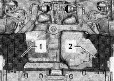
If present, remove stone guard -2-.
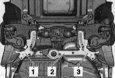
Place powertrain lift with universal gearbox clamp -VAG 1359/2- under subframe -1-. Place a suitable block -2- under the subframe -1-.
Remove bolt -1- on left and right.
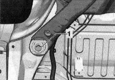
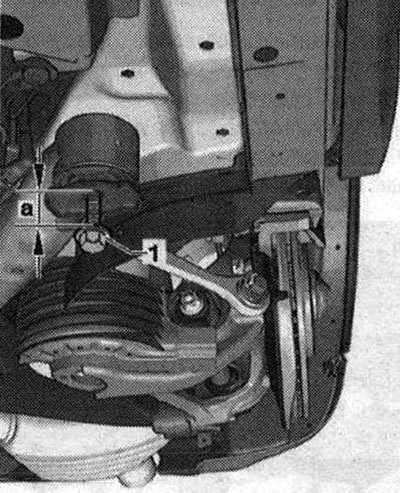
Screw the unscrewed bolts -1- on the right and left into the body as shown in the figure.
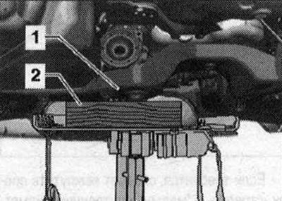
Screw in bolt -1- until distance -a- is 4 cm.
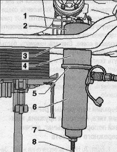
Unscrew bolt -2-. Lower the subframe only 4 cm. Press the final drive upwards via the propeller shaft -1-. At the same time, insert the mandrel -T40186/1- and the spindle -T10254/5- with nut -T10254/4- (will require the help of a 2nd mechanic).
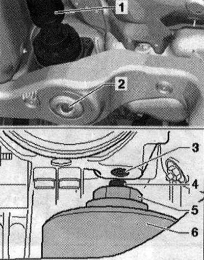
- 4. Lead screw -T10254/5-. Leadscrew journal facing down
- 5. Nut -T10254/4-
- 6. Stop -T40186/1-
When pressing out and pressing in the silent block, make sure that the lead screw -4- does not touch the threaded hole -3- of the main gear. If the lead screw -T10254/5- cannot be pushed through the through hole of the inner rod of the silent block, it must be drilled out. Drilling is carried out in several stages using drills of different diameters. When drilling, make sure that the drill does not damage the threaded hole -3- of the main gear; if necessary, place a suitable object. Install the drill -1- with the drill shown in the figure on the silent block -2- and carry out drilling in several stages.
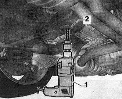
Stage 1, drill 11 mm, stage 2, drill 11.5 mm, stage 3, drill 12 mm.
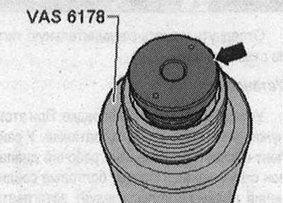
If necessary, unscrew the support -T10205/13- and in return screw in the support with "small" internal diameter -arrow- from hydraulic cylinder -VAS 6178-.
Install the tools, as shown in the figure, on the front silent block.
- 1. Nut -T10254/4-
- 2. Stop -T40186/1-
- 3. Subframe
- 4. Pipe -T40033/3-
- 5. Support ring -T10205/4-
- 6. Hydraulic cylinder -VAS 6178-
- 7. Nut -T10254/4-
- 8. Lead screw -T10254/5-. The lead screw journal faces down.
Attention. Hold hydraulic cylinder -VAS 6178- while pressing out. The silent block is disconnected "jerk". Falling tools and silent block can cause injury!
Installation
Install in reverse order. The following must be taken into account: before installing the silent block, make sure that the lead screw -T10254/5- passes through the through hole in the inner rod of the silent block. If the lead screw -T10254/5- cannot be pushed through the through hole of the inner rod of the silent block, it must be drilled out. It is easy to clamp the new silent block -2-, as shown in the figure, in a horizontal position in a vice -1- with protective jaw pads (avoid damaging the outer bushing of the silent block). Install a drill -3- with a drill, as shown in the figure, on the silent block -2- and drill in several stages.
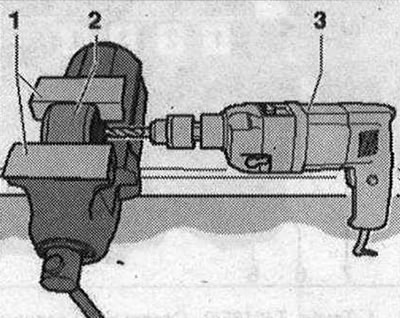
Stage 1, drill 11 mm, stage 2, drill 11.5 mm, stage 3, drill 12 mm.
Place a continuous mark across the grooves -arrow-, a = 90°.
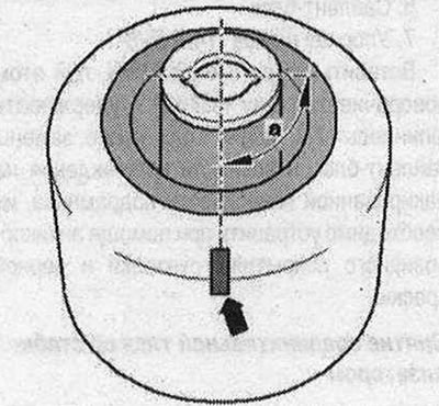
The mark is necessary to align the silent block relative to the subframe. When tightening the support, the grooves are closed with a tool. Insert the silent block with a self-applied mark -arrow- into the subframe so that the mark accurately indicates the direction of movement. Install the tools, as shown in the figure, on the front silent block.
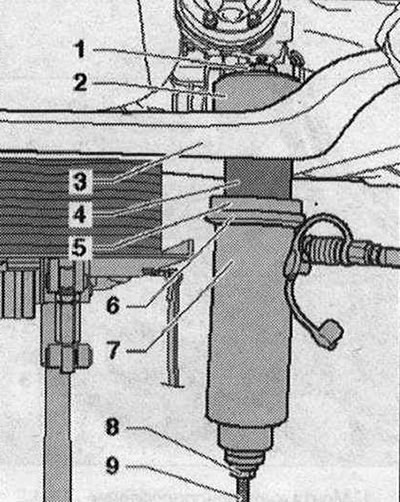
- 1. Nut -T10254/4-
- 2. Stop -T40Q33/7-
- 3. Subframe
- 4. Silent block
- 5. Thrust washer -T40186/3-
- 6. Support ring -T10205/4-
- 7. Hydraulic cylinder -VAS 6178-
- 8. Nut -T10254/5-
- 9. Lead screw -T10254/4-. The lead screw journal faces down.
Press the silent block all the way into the subframe. Perform a visual check of the subframe for damage to the paintwork. If, after replacing the silent blocks, damage occurs on the varnished surface of the subframe, they must be repaired using an anti-corrosion coating, primer and black paint. Install in reverse order.
Visitor comments