
Table of contents: Preload of differential bearings ↓ Adjusting the lateral clearance in… ↓
Adjustment is made only when replacing parts that directly affect the change in clearance: clutch housing, rear gearbox cover, differential tapered roller bearings, differential housing and final drive.
Preload of differential bearings
The differential bearings must be mounted with a preload of 0.50 mm, which is ensured by selecting the thickness of the adjusting rings "Si" and "S2" (see diagram), which simultaneously determine the lateral clearance in the engagement of the main transmission gears.
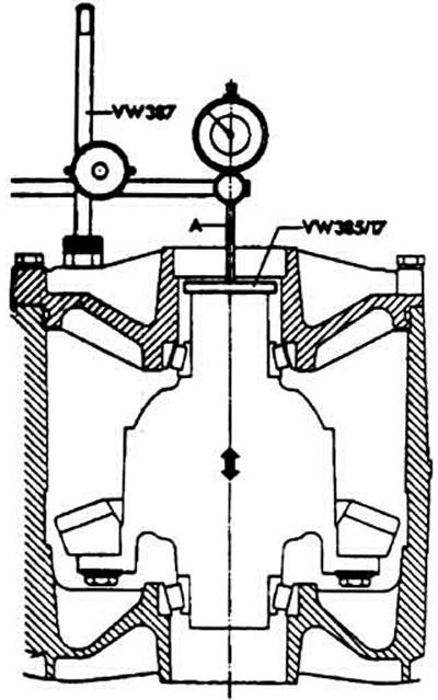
Measuring differential axial movement when adjusting differential bearing preload
Remove the differential output shaft seal using some kind of lever.
Press out the outer rings of the tapered roller bearings using a Kukko 21/7 type internal gear puller and a support mandrel.
Remove the differential bearing adjusting rings.
Press the bearing outer races without adjusting rings until they stop using a mandrel. It is best to use a set of mandrels 30-505 and 30-20 for pressing the bearing outer race on the side of the driven gear ring gear and a set of mandrels VW 295 and VW 511 for pressing the bearing outer race on the opposite side.
Install the differential into the clutch housing without the speedometer drive pinion. The driven pinion should be on the left side opposite the differential bearing cap.
Replace the differential bearing cover and tighten its mounting bolts crosswise to 2.5 kgf·m. The cover should be facing up.
Install the VW 385/17 support mandrel onto the differential case (see diagram).
Install the VW 387 indicator stand and secure the indicator with a 30 mm extension to it.
Place the indicator leg on the support mandrel with a preload of 1 mm, and fix the indicator in this position, setting its arrow to zero.
Raise and lower the differential and use the indicator to determine the differential axial displacement, which, for example, is 1.42 mm.
Warning: To avoid self-alignment of the bearings, do not rotate the differential when measuring its axial movement. Otherwise, the indicator readings will be incorrect.
According to the formula So6=A+B calculate the total thickness of the adjusting rings S1 and S2, where:
So6 - total thickness of differential bearing adjusting rings;
A is the value of the differential axial displacement;
B is the value of the differential preload.
Example: The indicator reading when moving the indicator is 1.42 mm, the value of the differential bearing preload is 0.50 mm.
So6 = 1.42 + 0.50 - 1.92 mm
Install the ring of thickness "S06" equal to 1.92 mm under the outer race of the tapered roller bearing in the cover instead of the adjusting ring "S2".
Tighten the differential cover mounting bolts.
Lubricate the differential bearings with transmission oil.
Measure the torque of resistance to turning of the differential with a dynamometer. It should be at least 250 N·cm for new bearings, and at least 30 N·cm for worn-in ones.
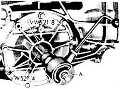
Measuring the torque of resistance to rotation of differential bearings
Adjusting the lateral clearance in the engagement of the main gear gears
Install the secondary shaft, press in the outer bearing pads with adjusting rings "S3" and "S4"
Install the differential with a washer of thickness "So6" pressed into the differential bearing cover instead of the adjusting ring "S2".
Rotate the differential in both directions to self-align the bearings.
Set the indicator to measure the side clearance in the final drive gear engagement with the differential rotating and the secondary shaft locked. The clearance should be measured at a diameter of 79 mm from the differential axis (the nominal gap should be within 0.10-0.20 mm).
Turn the driven gear to the stop and set the indicator to the zero position. Return the driven gear back by turning it to the stop and measure the lateral clearance between the teeth of the driving and driven gears. Record the indicator readings.
Repeat the above operation three times, each time turning the driven gear 90° and unlocking the secondary shaft.
Warning: If the measured values differ by more than 0.06 mm, the driven gear or main pair is not installed correctly. Check the correct assembly and replace the main pair if necessary.
Calculate the average value of the lateral clearance between the teeth of the driving and driven gears.
Example. Let's assume that the side clearance value at the first measurement is 0.84 mm, at the second - 0.85 mm, at the third - 0.84 mm, at the fourth - 0.83 mm, i.e. the front clearance value is (0.84 + 0.85 + 0.84 + 0.83): 4 = 0.84 mm. Calculate the thickness of the adjusting ring "S2" using the formula S2 = So6 - A + B. Where:
S2 — thickness of the adjusting ring installed under the outer ring of the differential bearing on the side opposite the toothed ring of the driven gear;
So6 — total thickness of adjusting rings "S1" and "S2";
A is the value of the average lateral clearance between the teeth of the driving and driven gears;
B — calculated thickness of ring "S2" (constant), equal to 0.15 mm.
Example: In our example, "So6" is 1.92 mm, "A" is 0.84 mm, "B" is 0.15 mm.
S2 = 1.92 - 0.84 + 0.15 = 1.23 mm
Calculate the thickness of the adjusting ring "Si" for the outer ring of the differential bearing, installed on the side of the toothed ring of the driven gear, using the formula S1=So6-S2.
Example: In our example, "So6" is 1.92 mm. "S2" is 1.23 mm.
S1 = 1.92 - 1.23 = 0.69 mm
Since the tolerance limits for the thickness of the adjusting rings are known, in all cases the calculated thickness of the adjusting rings can be selected with high accuracy.
Measure the thickness of the adjusting rings around the circumference with a micrometer at several points. Also, make sure that there are no burrs or other defects on the surface of the rings. Install only good quality adjusting rings of the required thickness "S1" and "S2". Perform a control measurement of the lateral clearance between the teeth of the driving and driven gears at four points around the circumference. The clearance should be within 0.10-0.20 mm.
Warning: The measurement results should not differ from each other by more than 0.65 mm.
[The article was copied from the website: AUDIMANUAL.ru]