
Table of contents: KP type 016 ↓ KP type 012 ↓
KP type 016
Checking the adjustment of the gear shift control lever
Engage 1st gear.
Pull the gearshift lever to the left. Release the lever - under the action of the spring it should move in the opposite direction by about 5-10 mm.
Perform the same operation by engaging V gear and moving the lever to the right: the spring should also move the lever to the left by about 5-10 mm.
Make sure that when I or V gear is engaged, the gearshift lever moves back approximately 5-10 mm. If the stroke is greater, adjust it by lateral movement of the movable stop in the oval holes.
Adjusting the gear shift control mechanism
Remove the gear shift knob and boot.
Place the gear shift lever in neutral position.
Disconnect the lower part of the gear shift rod from the spherical head of the gear selector lever.
Remove the connecting rod.
Adjust the position of the gear selector shaft lever as shown in the photo. Tighten the set bolt until the knurled end of the lever is flush with the gear selector shaft.
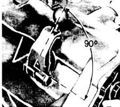
Position of the gear selector lever
Adjust the length "b" (see photo) between the centers of the holes of the connecting rod ends to 134 mm.
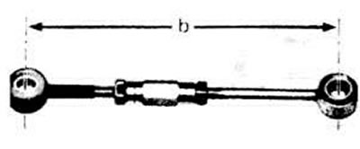
The distance "b" between the centers of the holes of the ends of the connecting rod of the gearshift mechanism should be equal to 134 mm
Place the lower end of the shift rod end onto the ball head of the shift rod lever.
Put the connecting rod back in place.
Align the centering holes of the stop and the gear shift lever support and tighten the bolts (see photo).
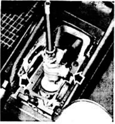
The arrows show the centering holes of the stop
Loosen the clamp.
Install template 3048 by inserting the template pins first into the free holes on the right, then on the left.
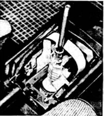
Template 3048 for adjusting the gear shift control mechanism
Check that the gear selector shaft on the right side of the transmission is in neutral position.
Remove the template.
Check that the gear shift lever position is adjusted correctly.
Replace the boot and gear shift knob.
KP type 012
Adjusting the gear shift control mechanism
Place the gear shift lever in neutral position.
Remove the gear shift knob and gear shift cover.
Loosen the bolt securing the reverse fork axle to the front push rod (marked "A" in the figure).
Set the gear shift lever to the vertical position.
Move the gear shift lever so that the ball head stop protrusions are the same distance from the ball joint housing.
Tighten the bolt securing the reverse fork axle to the front push rod.
Replace the trim cap and lever handle.