
Install the reverse intermediate lever mounting bolt.
Move the intermediate reverse lever in the direction indicated by the arrow in the photo and tighten the bolt securing the lever in the crankcase until it stops in the intermediate lever. The bolt and the threaded sleeve of the intermediate reverse lever should be in line.
Move the intermediate reverse lever towards the bolt. Unscrew the bolt until it clicks, i.e. until the beginning of the thread is passed. In any case, the bolt must be unscrewed by at least 1/4 of a turn.
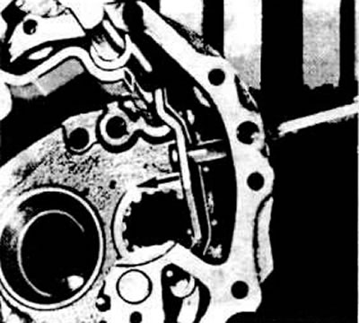
Adjusting the intermediate reverse lever
Tighten the reverse intermediate lever bolt to a torque of 3.5 kgf·m.
Shift into reverse several times and check the ease of operation of the intermediate reverse gear engagement mechanism.
Put the transmission into reverse.
Install the secondary shaft in place.
Install the 1st and 2nd gear shift fork with the rod and fully recess the secondary shaft.
Replace the spring latch and disengage reverse.
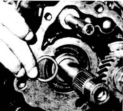
Remove the cylindrical roller bearing inner ring retaining ring from the input shaft.
Press on a press using a puller measuring 12-75 mm (for example, Kukko 17/1) inner ring of tapered roller bearing.
Install the primary shaft in place and insert the shift fork for III and IV gears into the cylindrical groove of the synchronizer sliding clutch.
Recess the input shaft completely.
Install the fork rod retainers.
Installing fork stem clamps
Install, after lubricating, the fork rod for shifting III and IV gears together with the cracker.
Insert spring pins into the holes of the shift forks of III and IV and I and II gears.
Install the fork steerer stop bolts with new cardboard washers.
Clamp the 4th gear of the secondary shaft in a vice with soft pads.
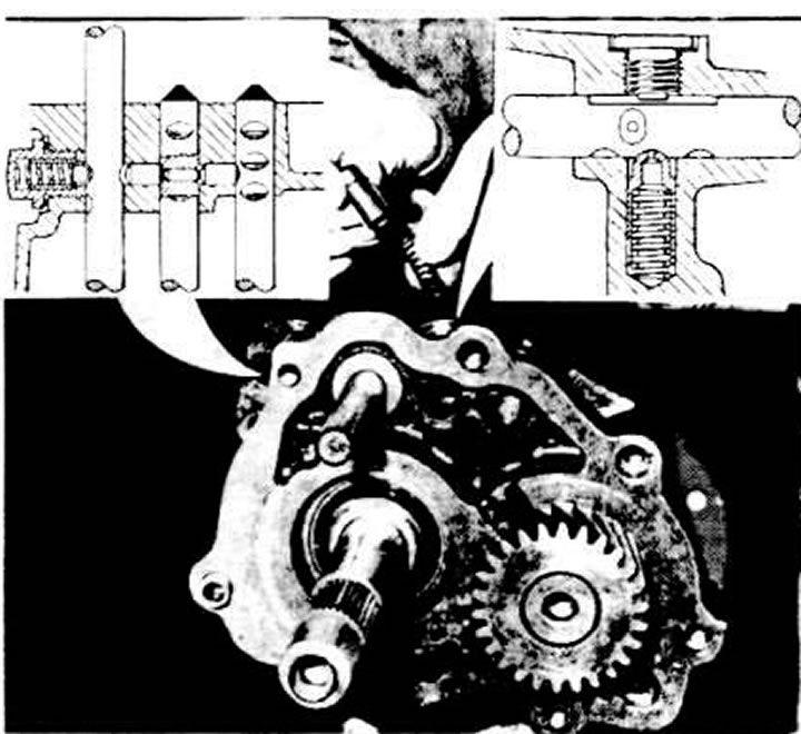
Measuring dimension "a" to determine the thickness of the adjusting washer of the V gear of the secondary shaft
Measure the value of dimension "a" (see photo) and determine the thickness of the adjusting washer according to the following table:
| Size "a", mm | Thickness of adjusting washer, mm |
| 8,35-8,64 | 1,10 |
| 8,65-8,94 | 1,40 |
| 8,95-9,24 | 1,70 |
| 9,25-9,54 | 2,00 |
| 9,55-9,84 | 2,30 |
Install the selected adjusting washer.
Heat the secondary shaft 5th gear to 120°C and install it in place, using a mounting sleeve if necessary. The shoulder of the 5th gear should point towards the main gear pinion.
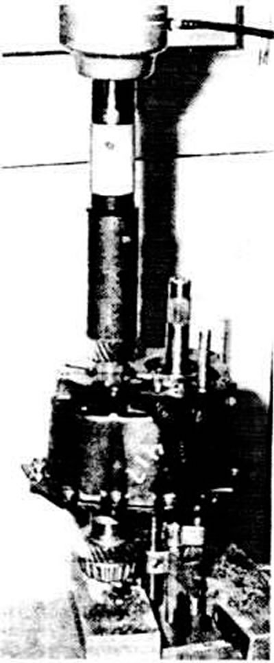
Pressing on the 5th gear
Install the washer and screw the hex bolt into the rear end of the secondary shaft, tightening the bolt to a torque of 5 kgf·m.
Clamp the input shaft in a vice with soft pads so that both shafts are in a vertical position.
Lightly grease the input shaft bearing cylindrical rollers and slide them out.
Heat the inner ring of the cylindrical roller bearing to about 120°C and press the ring onto the shaft. If necessary, press it until it stops using a mounting sleeve.
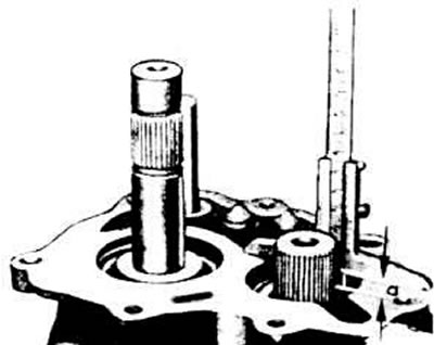
Determine the thickness of the cylindrical roller bearing inner ring retaining ring. Select the thickest ring and install it in place. The axial clearance should not exceed 0.05 mm.
Determination of the thickness of the retaining ring of a tapered roller bearing
Install the 5th gear sliding gear with the synchronizer sliding sleeve, needle bearing and fork.
Insert the spring pin into the hole in the 5th gear shift fork.
Install the synchronizer retaining ring and the 5th gear synchronizer locking ring.
Heat the toothed carriage of the 5th gear engagement to a temperature of about 120°C and put it on the end of the input shaft. If there is difficulty, press it on using the mounting sleeve until it stops.
Press the second inner race of the ball bearing into place using a mandrel.
Replace the mounting bushings and new sealing gasket.
Install the rear gearbox cover.
Press the first inner race of the ball bearing using a mandrel.
Tighten the input shaft hex bolt to 5 kgf·m.
Tighten the gearbox rear cover mounting bolts to a torque of 2.5 kgf·m
Insert a new plug into the hole in the rear gearbox cover.
Apply a thin layer of sealant to the mating surfaces of the transmission and clutch housings and join them together.
Press the mounting bushings into the crankcase holes and tighten the mounting bolts to a torque of 2.5 kgf·m
Apply a thin layer of "D3" sealant to the mating surfaces of the clutch housing and the gear selector shaft and install the gear selector shaft assembly.
Install the lever on the gear selection rod, while the end notch of the lever should be level with the rod at an angle of 90° (see photo).