
Table of contents: Disassembly ↓ Assembly ↓
Disassembly
Remove the 4th gear retaining ring and thrust washer.
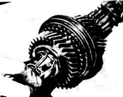
Removal the 4th gear sliding gear retaining ring
Remove the 4th gear sliding gear.
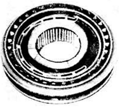
Sliding clutch assembly with synchronizer hub
Remove the 4th gear needle bearing.
Remove the 4th gear synchronizer locking ring
Remove the synchronizer retaining ring for III and IV gears.
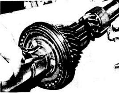
Removal the synchronizer retaining ring of III and IV gears
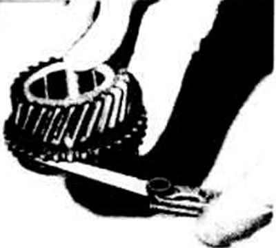
Press the III gear block with the sliding clutch and the III and IV gear synchronizer on a press.
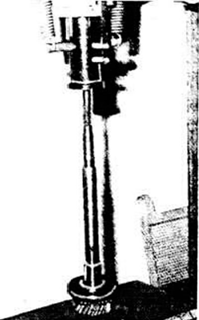
Pressing the gear of the third gear and the synchronizer hub of the third and fourth gears
Remove the needle bearing of the third gear from the shaft.
Assembly
Lubricate the 3rd gear needle bearing with hypoid oil and install it in place.
Check the wear of the 3rd gear synchronizer locking ring. To do this, slide the ring onto the conical part of the 3rd gear sliding gear and measure the axial clearance between the end of the locking ring and the end of the gear synchronizer ring gear with a feeler gauge, which should be at least 0.5 mm.
Checking the axial clearance between the end face of the locking ring and the end face of the synchronizer gear ring
Install the sliding gear of the 3rd gear and the locking ring of the synchronizer of the 3rd gear on the shaft.
If the sliding coupling has been disconnected from the hub, slide the sliding coupling onto the hub, install the crackers into the hub grooves and put the springs in place, moving the spring connectors at an angle of 120° relative to each other. The bent ends of the spring must be placed behind the projections of the crackers. Press the coupling assembly onto the shaft with the hub, directing the groove or wide 6 edge of the hub towards the sliding gear of the fourth gear. Turn the locking ring so that the ends of the crackers enter the grooves of the ring.
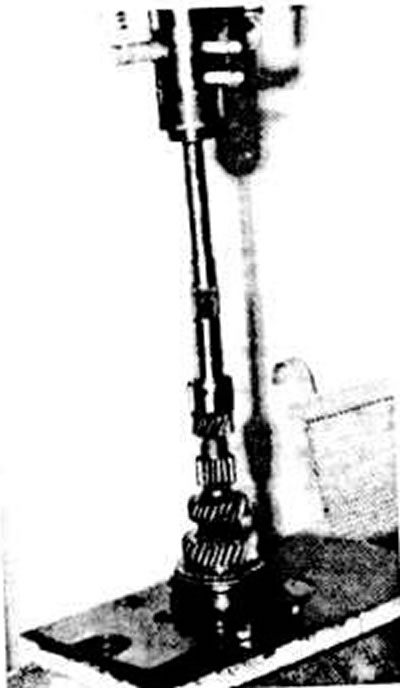
Pressing on the sliding sleeve of the synchronizer of III and IV gears together with the hub
Install the retaining ring and measure the synchronizer axial clearance with a feeler gauge, which should be within 0.00-0.04 mm. Select and install the retaining ring that provides the smallest clearance.
Measure the gap between the gears of the 2nd and 3rd gears with a feeler gauge, which should be within 0.10-0.35 mm; if necessary, check the adjustment of the axial clearance of the synchronizer.
Check the wear of the 4th gear synchronizer locking ring in the same way as is done for the 3rd gear synchronizer locking ring.
Install the 4th gear synchronizer locking ring, hypoid oil lubricated needle bearing, 4th gear sliding gear, thrust washer and snap ring.
Measure the axial clearance of the sliding gear of the fourth gear with a feeler gauge. It should be within 0.10-0.35 mm. Achieve the smallest clearance by selecting a retaining ring of the appropriate thickness.