
Repair Chevrolet Repair Toyota Repair Honda Repair AvtoVAZ Repair Mercedes-Benz Repair BMW Repair Opel
Home  |  Contacts  |  Sitemap  |    
English Русский
Български
Беларускі
Український
Српски
Hrvatski
Română
Polski
Slovenský
Magyar
AudiManual.ru


  • AUDI 80
  • AUDI 100
  • AUDI A3
  • AUDI A4
  • AUDI A6
  • AUDI A8
  • AUDI Q
  • OTHER
  • ARTICLES
C4 (1990-1994) C4 (1990-1994, petrol) C3 (1982-1990) C3 (1982-1990, petrol) C3 (1982-1990, diesel)

Disassembling the gearbox (Audi 100 C3)

  • Home
  • Audi 100
  • C3 (1982-1990, petrol)
  • Transmission
  • 5 speed gearbox 016 and 012
  • Disassembling the gearbox
            0
Note: When replacing parts that directly affect the position of the main drive pinion (tapered roller bearings, the main drive pinion itself or the gearbox housing), and also if there is no marking on the driven gear of the deviation "g" from the nominal position of the driving gear, before starting to disassemble the gearbox, measure the value "r" as indicated below.
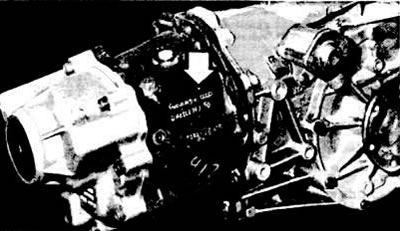

The arrow shows the gearbox marking

The arrow shows the gearbox marking


Drain the oil from the gearbox housing, clean the gearbox and install it on the assembly table.

Remove the gear selector lever.

Remove the gear selector shaft assembly.

After unscrewing the mounting bolts, separate the gearbox housing from the clutch housing.
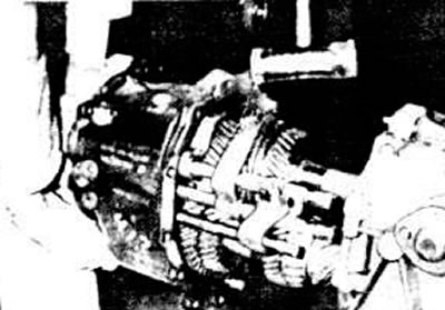
Separating the gearbox housing from the clutch housing

Separating the gearbox housing from the clutch housing


Remove the plastic plug from the rear gearbox cover using a screwdriver.

Clamp the input shaft in a vice with soft metal pads and remove the hex bolt from the rear end of the input shaft.

Clamp the gearbox housing in a vice.

Remove the bolts securing the rear gearbox cover.

Remove the rear cover of the gearbox housing, moving it with a plastic mallet if necessary, and remove the first inner race of the primary shaft ball bearing.

Using a two-lever puller, remove the toothed carriage 2 (see photo) of the 5th gear engagement together with the second inner ring 1 of the primary shaft ball bearing, then remove the locking ring 3 of the 5th gear synchronizer.
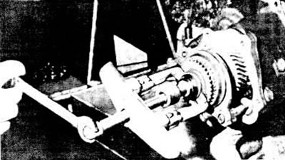
Removal the V-gear synchronizer tube carriage

Removal the V-gear synchronizer tube carriage


Knock out the spring pin from the 5th gear fork without damaging the fork rod socket in the crankcase wall.

Remove the 5th gear synchronizer sliding sleeve retaining ring from the primary shaft.
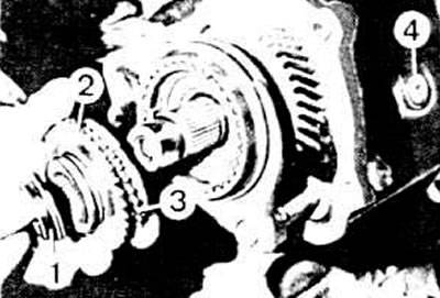
Removal 5th gear parts: 1 - second inner bearing ring; 2 - toothed carriage for engaging the 5th…

Removal 5th gear parts: 1 - second inner bearing ring; 2 - toothed carriage for engaging the 5th gear; 3 - V gear synchronizer locking ring; 4 - intermediate reverse gear lever mounting bolt


Remove the 5th gear sliding gear together with the sliding sleeve, hub, needle bearing and 5th gear engagement fork.

Remove the stop bolts 1 (see photo) of the fork rods.
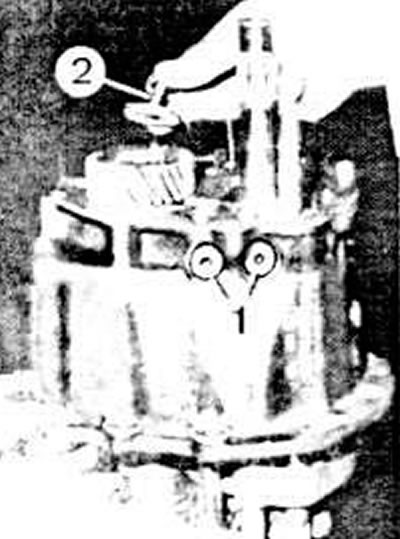
Thrust bolts 1 of the fork rods and hexagon bolt 2 of the rear end of the secondary shaft

Thrust bolts 1 of the fork rods and hexagon bolt 2 of the rear end of the secondary shaft


Clamp the 4th gear of the secondary shaft in a vice with soft metal pads and unscrew the hex bolt 2 from the end of the secondary shaft.

Press the 5th gear off the secondary shaft using a Kukko 20/10 type lever puller.

Remove the V gear adjusting washer.

Secure the gearbox housing in a vice with pads made of some material.

Knock out the spring pin from the 1st and 2nd gear shift fork rod linkage while holding the fork rod with a hammer.
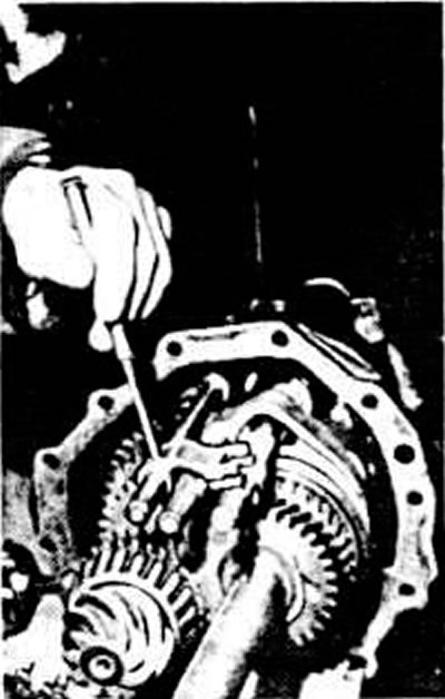
Removal the spring pin from the 1st and 2nd gear shift fork rod link

Removal the spring pin from the 1st and 2nd gear shift fork rod link


Turn the rod leash upward.

Knock out the spring pin from the III and IV gear shift fork. Remove the III and V gear fork rod. Remove the push rod and the retainer spring.

Remove the intermediate reverse gear lever mounting bolt.

Slightly extend the primary and secondary shafts out of the gearbox housing.

Remove the primary shaft together with the shift fork for III and IV gears.

Disconnect the reverse spring latch from the secondary shaft side and move it to the side. Remove the reverse lock.

Extend the secondary shaft so that the rod and the fork for shifting 1st and 2nd gears can be removed

Remove the secondary shaft by turning it around the axis.
The article was checked by auto expert Maxim Rybakov
This article is available at russian, bulgarian, belarusian, ukrainian, serbian, croatian, romanian, polish, slovak, hungarian

Share information:
Previous articles
Audi 100 C3: 5 speed gearbox 016 and 012
Next articles

Removal and installation the gearbox
Details of five-speed gearbox type 016
Tightening torques for main threaded connections
Detailed technical specifications of the transmission
Disassembly and assembly of the primary shaft
Disassembly and assembly of the secondary shaft
Removal and installation the differential
Secondary shaft bearing preload


Similar articles on other Audi car models:
General description of the mechanical gearbox Audi 80 B3 (1986-1991, petrol)
Visual inspection of the gearbox for leaks Audi A3 Type 8L (1996-2003)
Gearbox and final drive Audi A4 B5 (1994-2001, petrol)
Gearbox/ final drive Audi A6 C5 (1997-2004)
Visual inspection of gearbox tightness Audi A8 D2 (1994-2002)
Cylinder block from the gearbox side Audi Q5 Type 8R (2008-2017)
Fastening the gearbox to the engine Audi A2 (1999-2005)
Link to this page in different formats


Visitor comments

No comments yet


How much will 14 + 15 =


100(C4, 1990-1994) 
  • General information
  • User manual
  • Power unit
  • Engine repair
  • Ignition system
  • Fuel system (gasoline)
  • Fuel system (diesel)
  • Lubrication system
  • Cooling system
  • Exhaust system
  • Transmission
  • Clutch
  • Car gearbox
  • Drive shafts
  • Chassis
  • Car suspension
  • Steering
  • Wheels and tires
  • Brake system
  • Body
  • Ventilation and heating
  • Body repair
  • Electrical equipment
  • Power devices
  • Lighting and appliances
  • Electrical circuits
 
100(C4, 1990-1994, petrol) 
  • General information
  • Operation and maintenance
  • Power unit
  • Engine repair
  • Exhaust system
  • Cooling system
  • Supply system
  • Air filter
  • Mono-Motronic injection system
  • Digifant injection system
  • KE-III-Jetronic and KE-Motronic
  • MPI and MPFI injection system
  • Transmission
  • Clutch
  • Car gearbox
  • Chassis
  • Suspension and steering
  • Brake system
  • Wheels and tires
  • Body
  • Exterior
  • Interior
  • Electrical equipment
  • Fuses and relays
  • Power devices
  • Ignition system
  • Lighting and signaling
  • Equipment and devices
  • Electrical circuits
 
100(C3, 1982-1990) 
  • General information
  • User manual
  • Maintenance
  • Specifications
  • Power unit
  • Engines 4-cylinder
  • Engines 5-cylinder
  • Diesel engine
  • Cooling system
  • Power system (carburetor)
  • Power system (injector)
  • Fuel system (diesel)
  • Transistor ignition system
  • Electronic ignition system
  • Transmission
  • Clutch
  • 4 speed gearbox 014
  • 5 speed gearbox 013 and 093
  • 5 speed gearbox 016 and 012
  • Shift mechanism KP 016
  • Automatic transmission
  • Front wheel drive
  • Chassis
  • Front suspension
  • Rear suspension
  • Steering
  • Brake system
  • Body
  • Body elements
  • Electrical equipment
  • Lighting and appliances
  • Power devices
  • Electrical circuits
 
100(C3, 1982-1990, petrol) 
  • General information
  • Maintenance and operation
  • 4 cylinder engine
  • Engine repair
  • Cooling and lubrication system
  • Supply system
  • Ignition system
  • 5 cylinder engine
  • Engine repair
  • Cooling and lubrication system
  • Supply system
  • Ignition system
  • Transmission
  • Clutch and drive shafts
  • 4 speed gearbox 014
  • 5 speed gearbox 013 and 093
  • 5 speed gearbox 016 and 012
  • Automatic gearbox
  • Chassis
  • Steering
  • Front suspension
  • Rear suspension
  • Brake system
  • Body
  • Body elements
  • Doors, locks and windows
  • Body repair
  • Electrical equipment
  • Equipment and devices
  • Power devices
  • Electrical circuits
 
100(C3, 1982-1990, diesel) 
  • General information
  • User manual
  • Maintenance
  • Troubleshooting
  • Power unit
  • Engine in a car
  • Engine removed
  • Cooling system
  • Fuel system
  • Exhaust system
  • Starting and charging
  • Preheating
  • Transmission
  • Clutch
  • Mechanical gearbox
  • Automatic gearbox
  • Drive shafts
  • Chassis
  • Brake system
  • Suspension
  • Steering
  • Body
  • Exterior
  • Interior
  • Electrical equipment
  • Equipment and devices
  • Electrical circuits
 
AudiManual.ru © 2017-2026 · Mobile version · Feedback · Sitemap: EN BG BY UA RS HR RO PL SK HU · Site search · News and articles
80 B2 · 80 B3 petrol · 80 B3 · 80 B4 · 100 C3 diesel · 100 C3 petrol · 100 C3 · 100 C4 petrol · 100 C4 · A3 Type 8L · A4 B5 petrol · A4 B5 · A4 B6 petrol · A4 B6 · A4 B7 · A4 B8 · A6 C4 · A6 C5 · A6 C5 Allroad · A8 D2 · Q5 Type 8R · Q7 Typ 4L · Audi A2 ·
This site uses cookies 🍪. Click the button to accept this fact.