
2. Insert the 1/2 gear shift rod, install the output shaft.
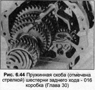
3. Connect the spring clip disconnected from the reverse synchronizer pin, disengaging the reverse gear.
4. Position the 3/4 gear shift fork engaging the slot in the 5/3 gear shift rod.
5. Remove the input shaft bearing inner race and retaining ring.
6. Partially install the input shaft, insert the 3/4 shift fork into the clutch sleeve and push the input shaft into place.
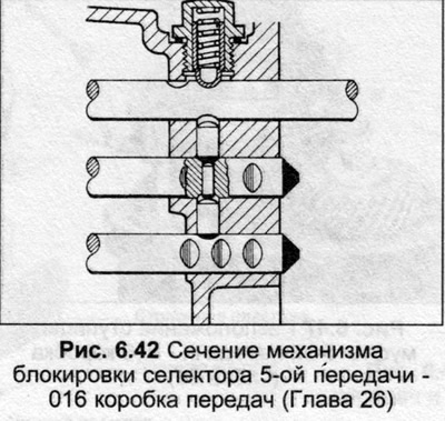
7. Move each gear shift rod to neutral position, check that the locking pins are positioned as shown in Fig. 6.42.
8. Insert the 3/4 shift rod, insert the lock pin. Lubricate the pin before installation.
9. Secure the 3/4 shift fork by inserting a new roll pin.
10. Secure the 1/2 gear shift rod.
11. Install the lock screws with new paper gaskets and tighten them.
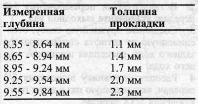
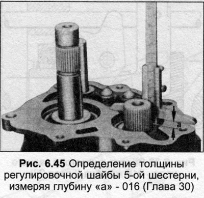
12. Clamp the output shaft with the 4th gear in a vice, calculate the thickness of the 5th gear adjusting washer by measuring the depth "a" (Fig. 6.45). The required thickness of the gasket will be as follows:
13. Once the spacer has been selected and installed, the 5th gear must be heated to 120°C to allow it to be installed on the shaft. Insert the gear so that it is positioned against the bushing. Install the bolt and flat spacer, tighten the bolt to the torque specified in the Specifications. On later models the bolt must be replaced.
14. Clamp the input shaft in a vice so that the shafts are vertical.
15. Lubricate the input shaft support rollers and press them in.
16. The inner ring of the bearing must be heated to 120°C and installed on the shaft, guiding it down through the rollers.
17. Once the inner ring is installed, secure it with a snap ring of the appropriate thickness. Select a snap ring to provide an axial clearance of no more than 0.05 mm. Select the thickest snap ring that will fit into the groove and provide the correct axial clearance and install it. Snap ring thicknesses include 1.35, 1.40 and 1.45 mm.
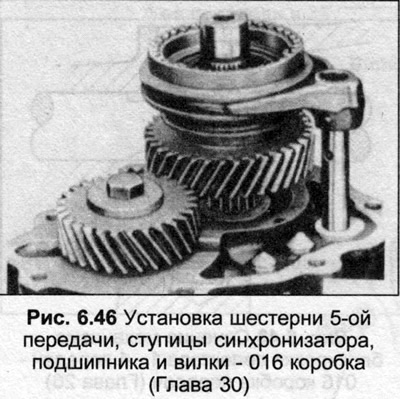
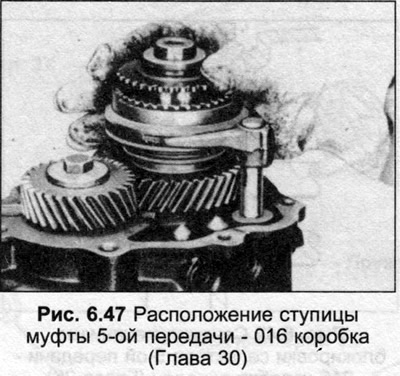
18. Install the 5th gear with the synchronizer hub, needle bearing and engagement fork. Secure the fork to the shaft using a new cylindrical pin.
19. Install the retaining ring, position the 5th gear synchronizer ring.
20. To install the hub bushing onto the 5th gear assembly, heat it to 120°C. Slide the bushing into place, then install the inner race onto the input shaft.
21. Position the new gasket, install the gear mount housing cover.
22. Position the remaining input shaft bearing inner race.
23. After installing the inner ring, install the flat gasket and the mounting bolt, tighten it to the tightening torque specified in the Specifications. On later models, the bolt must be replaced.
24. Install the gear retainer to cover cap bolts and tighten to the torque specified in the Specifications. Install the new cover cap into the hole at the end of the cover.
25. Lubricate the mating surfaces of the gear mount and gearbox with sealant. Connect the gear mount to the gearbox by placing it on the mounting pins, insert the clamp bolts, and tighten them to the tightening torque specified in Specifications.
26. Install the selector lever.
27. On later models the selector lever and shaft assembly have been modified. The small selector shaft housing is not fitted. The springs and linings pushing the lever to the 3/4 gear mechanism have also been modified (and which prevent the possibility of forward displacement from the 5th gear to the reverse gear).
28. The last typical selector lever is attached to the shaft with a cone bolt. The cone bolt is self-locking and must be replaced during overhaul.
[The original publication in its entirety is posted on the website: AudiManual.ru]