
Table of contents: Gear Shift Lever Assembly ↓ Gear shift rods ↓
Note: Before starting, see. Chapter 31, paragraph 1.
1. The shift rod consists of two main parts: the shift lever assembly and the rod rods.
Gear Shift Lever Assembly
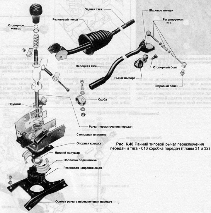
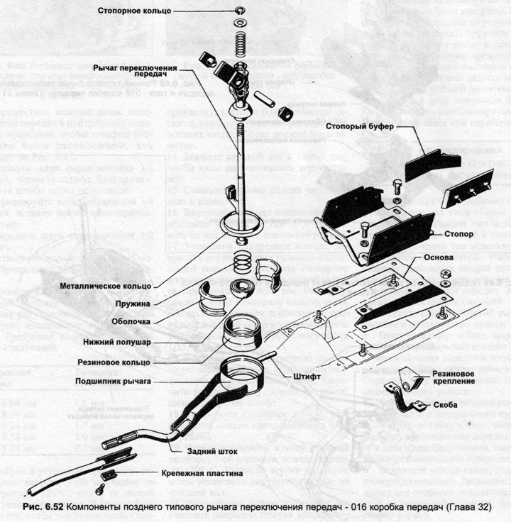
2. Remove the gear shift lever as described in Chapter 31.
3. Unscrew the lever button, remove the retaining ring, remove the spring from the lever.
4. On early versions, mark the alignment of the locking plate to the cover plate, unscrew the four bolts and separate the locking plate. Do not disassemble the lower bearing unless necessary. Push the rubber guide out of the lever base, spread the plastic skeletons apart and remove the gearshift lever, upper and lower hemispheres. On later versions, it is necessary to release the notch with a chisel around the lower bearing, after which the annular rubber guide can be removed.
5. When assembling, lubricate all rubbing surfaces with special lubricant AOS 126 000 05.
6. When assembling the rubber guide, place it with the narrow end up and insert the two frames. Press in the lower half-ball, then the spring, and finally the upper half-ball.
7. Slide the rubber ring down the lever or, on later versions, the rear pushrod. On later versions, install the metal ring and secure the assembly.
8. Install the lock plates, cover plate and control arm base, aligning with the previously made marks.
9. Install the spring, snap ring, then screw on the gear shift button.
10. Install the gear shift lever assembly as described Chapter 31.
Gear shift rods
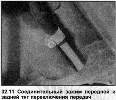
11. To remove the front shift rod, remove the ball joint of the adjusting rod from the shift rod, disconnect the rod from the gear shift lever. Loosen the clamp, remove the front rod from the rear shift rod (photo), remove it from under the car. Installation is carried out in the reverse order.
12. To remove the rear shift rod, remove the central console, unscrew the nut and bolt securing the rod to the gearshift lever. Loosen the clamp, remove the rear shift rod from the front shift rod, and remove the rod upwards into the vehicle interior. Installation is carried out in the reverse order.
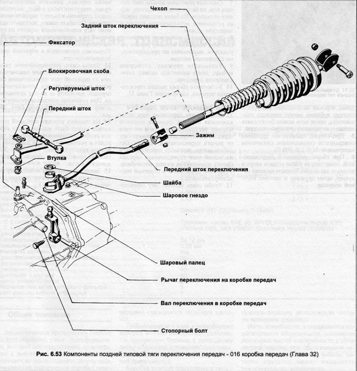
13. To remove the adjusting rod, disconnect it with the ball end from the front gearshift rod and gearshift lever studs, remove it from under the car. When installing, always check the length of the rod, which should be 134 mm.
14. On later versions, the front pushrod can be removed by removing the locking bracket in the gearbox and the clamp bolt and plate in the rear pushrod connection. Installation is carried out in the reverse order.
15. The rear pushrod on later versions is removed together with the gear shift lever (Chapter 31).
(The original version is on the portal «AUDIMANUAL.ru»)