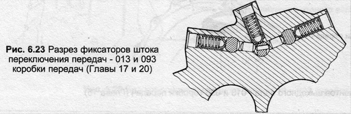
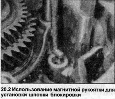
2. With the gear mounting element placed on the bench, install the locking keys in their locations as shown in Fig. 6.23. If the selector locks were removed, they can be installed later using a magnetic rod (photo).
3. Place the 1/2 gear engagement fork and the rod with the 1/2 gear synchronizer sleeve on the driven shaft and lower them simultaneously into the gear fastening element housing.
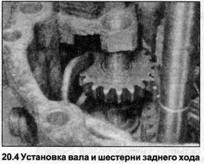
4. Insert the reverse gear shaft, and at the same time position the reverse gear between the teeth of the transmission lever (photo). Insert the shaft completely.
5. Fold the 3/4 gear fork with the 3/4 gear synchronizer sleeve on the input shaft, lower them into the gear retainer and engage them with the output shaft gears. Make sure that the synchronizer sleeves are located centrally in the hubs, otherwise the locking crackers may pop out.
6. Insert the small locking key into the 3/4 shift rod, secure it with grease. Insert the 3/4 shift rod into the gear retainer through the gear shift fork.
7. Align the holes, insert the cylindrical pin into the end of the fork rod.
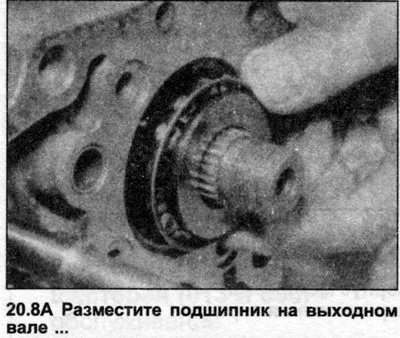
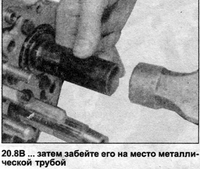
8. Supporting the front ends of the shafts, install the inner bearing ring on the output shaft, insert it with a metal pipe until it contacts the outer ring (photo).
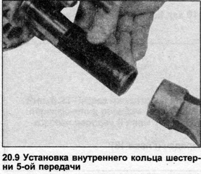
9. Position the 5th gear thrust washer on the input shaft, move the 5th gear inner ring (photo). The inner ring can be preheated to 120°C to facilitate installation.
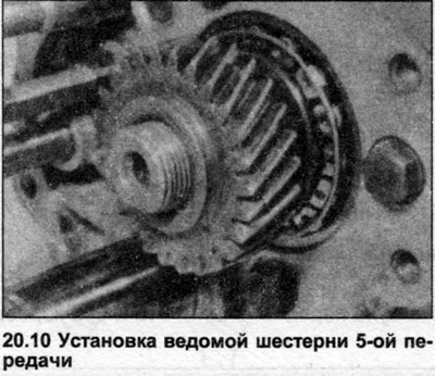
10. Position the driven 5th gear on the output shaft, insert it completely into the slots using a metal pipe (photo). The gear can be preheated like the ring in step 9 to facilitate installation.
11. Position the 5th gear needle bearing on the input shaft and lubricate them with transmission oil.
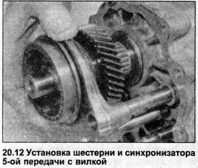
12. Assemble the 5th gear fork with the 5th gear synchronizer sleeve/gear, place the assembly through the shift rod to the input shaft (photo).
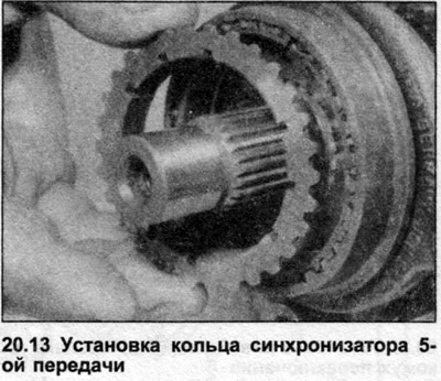
13. Install the 5th gear synchronizer ring onto the synchronizer (photo).
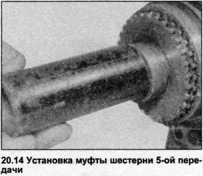
14. Install the coupling, push it completely onto the grooves using a metal pipe (photo). The coupling can be preheated to 120°C to facilitate installation.
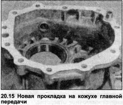
15. Position the new gasket on the final drive housing (photo).
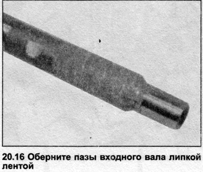
16. Wrap the end of the input shaft with film (photo). Lower the gear retainer onto the main gear housing and insert the bolts with the mounting bracket.
17. Insert the dowel pins, tighten the bolts in a diagonal sequence to the tightening torque specified in the Specifications.
18. Engage 5th gear by moving the synchronizer sleeve (that is, leaving the gearshift rod in neutral position) and 1st gear by extending the 1/2 gear shift rod. The input and output shafts are now locked.
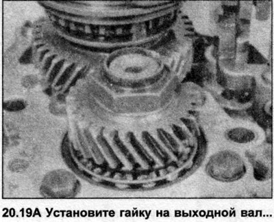
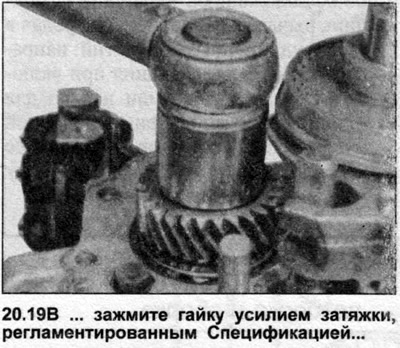
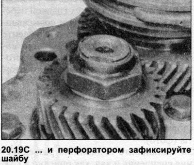
19. Tighten the output shaft nut to the tightening torque specified in the Specifications (photo). After tightening the nut, return the mechanisms to the neutral position.
20. Align the holes, insert the cylindrical pin into the 5th gear shift fork.
21. Position the 1/2 gear selector clamp on the rod near the end position, but do not install the roll pin at this stage.
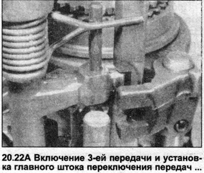
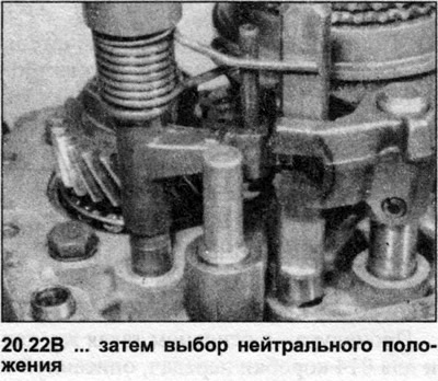
22. Pull out the shift rod to engage the 3rd gear, then insert the main shift rod including the ends of the springs into the 3/4 shift rod, and with the pin in the notch, push the main shift rod into the bushing. After installation, push the 3/4 shift rod to the neutral position (photo).
23. Align the holes, insert the roll pin into the 1/2 gear selector clamp.
24. Position the new gasket on the gear retainer, lower the shift housing. If necessary, tap the inner race of the ball bearing lightly to position it on the end of the input shaft.
25. Insert the bolts with hangers, lubricating the threads with sealant. Tighten the bolts in a diagonal sequence.
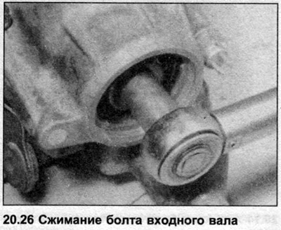
26. Insert the bolt and thick washer into the end of the input shaft, tighten to the tightening torque specified in Specifications, using the method described in Chapter 13, point 7 (photo).
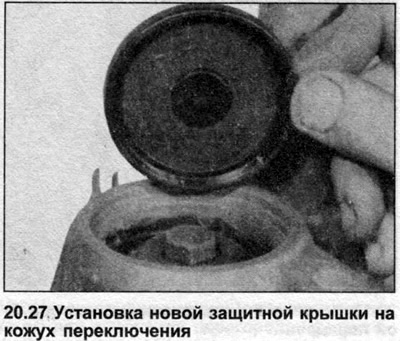
27. Clean the recess and insert the new cover plate (photo).
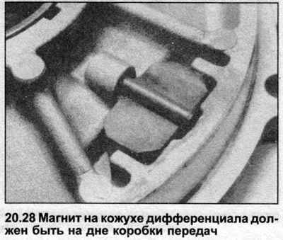
28. If the differential is not already installed, lower it into the final drive housing. Clean the cover and housing mating surfaces and apply sealant. Position the cover on the housing, insert and tighten the bolts in a diagonal sequence to the torque specified in Specifications. Note that the magnet on the cover should be placed at the bottom (photo).
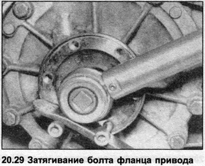
29. Insert the drive flanges on each side of the differential, tighten the bolts (photo).
30. Install the clutch release bearing and shaft as described in Section 5.
31. Insert and tighten the reversing light switch, secure the wiring.
32. Fill the gearbox with oil.