Repair Chevrolet Repair Toyota Repair Honda Repair AvtoVAZ Repair Mercedes-Benz Repair BMW Repair Opel
Home  |  Contacts  |  Sitemap  |    
English Русский
Български
Беларускі
Український
Српски
Hrvatski
Română
Polski
Slovenský
Magyar
AudiManual.ru


  • AUDI 80
  • AUDI 100
  • AUDI A3
  • AUDI A4
  • AUDI A6
  • AUDI A8
  • AUDI Q
  • OTHER
  • ARTICLES
C4 (1990-1994) C4 (1990-1994, petrol) C3 (1982-1990) C3 (1982-1990, petrol) C3 (1982-1990, diesel)

Gearbox (016) — disassembly into main blocks (Audi 100 C3)

  • Home
  • Audi 100
  • C3 (1982-1990, diesel)
  • Transmission
  • Mechanical gearbox
  • Gearbox (016) — disassembly into main blocks
            0
1. Remove the gearbox drain plug, drain the oil, install the plug. Clean the gearbox housing from dirt.

2. Mark the position of the gear selector lever on the grooves, loosen the clamp bolt, and disconnect the selector lever.

3. Unscrew the bolts of the pickup shaft cover, remove the cover, and take out the pickup shaft assembly.

4. Remove the bolts securing the bearing housing to the gearbox housing, push out the two mounting pins.

5. Extend the selector shaft as far as possible so that it can be disconnected from the clamps on the gearshift rods and then separate the bearing carrier housing with the mechanism assembly from the gearbox housing.

6. Remove the cover from the end of the bearing carrier. If a metal cover is installed, knock out the O-ring with a drift and remove it. If a rubber plug is installed, punch the center of the plug with a large screwdriver and pry the plug out. If the transmission has a metal cover, do not install a rubber plug because it will block the oil hole.

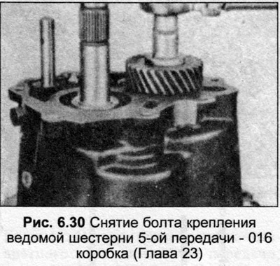
7. Clamp the input shaft in a vice, loosen and remove the hex bolt from the end of the shaft.

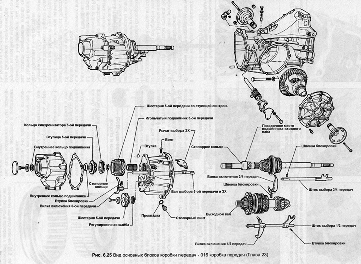
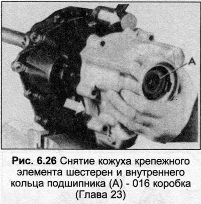
8. Support the gear mount housing (bearing), unscrew and remove the twelve mounting bolts. Remove the casing. Remove the inner ring A (Fig. 6.26) of the ball bearing.

8. Support the gear mount housing (bearing), unscrew and remove the twelve mounting bolts. Remove…


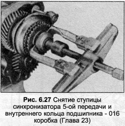
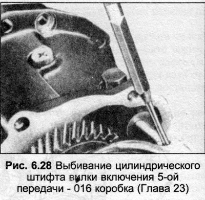
9. Using a universal puller, pull off the 5th gear synchronizer hub and the secondary shaft bearing inner race, then the synchronizer ring. Drive out the cylindrical pin securing the 5th gear shift fork.


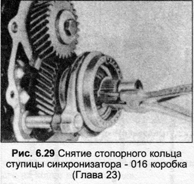
10. Remove the snap ring securing the 5th gear, then remove the 5th drive gear and shift fork, leaving the 5/3rd gear shift rod in the fastener housing.

11. Remove the shift rod lock screws, carefully clamp the 4th gear/pinion in a vice (equipped with soft sponges for protection). Loosen and remove the pinion bolt.

12. To get the 5th driven mechanism, you need an extractor. After removing the mechanism, remove the adjusting washer.

13. Support the free end of the 1/2 gear shift fork shaft, push out the cylindrical pin securing the gear shift fork to the shaft.

14. Press out the 3/4 shift fork cylindrical pin. Remove the 3/4 shift rod, leave the shift fork on the sleeve. Do not lose the locking key.

15. Unscrew and remove the lever bolt.

16. Now the gears and input shaft should be slightly pulled out. Then remove the input shaft with the 3/4 gear engagement fork.

17. Disconnect the reverse gear spring clip on the gear side and rotate around to remove the 1/2 shift fork and rod. Remove the output shaft.

18. Disassemble the gearbox housing as follows. First insert a suitable rod through one of the drive flange bolt holes so that the rod is positioned against one of the ribs of the cover and to prevent the flange from rotating, then unscrew the central flange bolt. Repeat the action on the other drive flange, then remove the flange shafts. Mark each shaft to avoid confusion during installation.

19. Remove the differential housing bolts, remove the cover, and remove the differential.

19. Remove the differential housing bolts, remove the cover, and remove the differential.


19. Remove the differential housing bolts, remove the cover, and remove the differential.


19. Remove the differential housing bolts, remove the cover, and remove the differential.


19. Remove the differential housing bolts, remove the cover, and remove the differential.


19. Remove the differential housing bolts, remove the cover, and remove the differential.


19. Remove the differential housing bolts, remove the cover, and remove the differential.


A link to the original source is available on the website: AUDIMANUAL.ru
The article was checked by auto expert Nikita Rudakov
This article is available at russian, bulgarian, belarusian, ukrainian, serbian, croatian, romanian, polish, slovak, hungarian

Share information:
Previous articles
Audi 100 C3: Mechanical gearbox
Next articles

Gear shift rod (013 and 093) — disassembly and assembly
Gear Shift Lever (013 and 093) — Removal, Installation and…
Gearbox (013, 093) — assembly
5th Gear Components (013 & 093) — Service
Input shaft (016) — disassembly and assembly
Output shaft (016) — disassembly and assembly
Bearing/Gear Fastener (016) — Service
Gearbox/Final Drive Housing — Service (016)


Similar articles on other Audi car models:
Disassembly and assembly of the gearbox Audi 80 B2 (1979-1986)
Visual inspection of the gearbox for leaks Audi A3 Type 8L (1996-2003)
Disassembly and assembly of the gearbox Audi A4 B8 (2007-2015)
Gearbox/ final drive Audi A6 C5 (1997-2004)
Visual inspection of gearbox tightness Audi A8 D2 (1994-2002)
Cylinder block from the gearbox side Audi Q5 Type 8R (2008-2017)
Fastening the gearbox to the engine Audi A2 (1999-2005)
Link to this page in different formats


Visitor comments

No comments yet


How much will 13 + 24 =


100(C4, 1990-1994) 
  • General information
  • User manual
  • Power unit
  • Engine repair
  • Ignition system
  • Fuel system (gasoline)
  • Fuel system (diesel)
  • Lubrication system
  • Cooling system
  • Exhaust system
  • Transmission
  • Clutch
  • Car gearbox
  • Drive shafts
  • Chassis
  • Car suspension
  • Steering
  • Wheels and tires
  • Brake system
  • Body
  • Ventilation and heating
  • Body repair
  • Electrical equipment
  • Power devices
  • Lighting and appliances
  • Electrical circuits
 
100(C4, 1990-1994, petrol) 
  • General information
  • Operation and maintenance
  • Power unit
  • Engine repair
  • Exhaust system
  • Cooling system
  • Supply system
  • Air filter
  • Mono-Motronic injection system
  • Digifant injection system
  • KE-III-Jetronic and KE-Motronic
  • MPI and MPFI injection system
  • Transmission
  • Clutch
  • Car gearbox
  • Chassis
  • Suspension and steering
  • Brake system
  • Wheels and tires
  • Body
  • Exterior
  • Interior
  • Electrical equipment
  • Fuses and relays
  • Power devices
  • Ignition system
  • Lighting and signaling
  • Equipment and devices
  • Electrical circuits
 
100(C3, 1982-1990) 
  • General information
  • User manual
  • Maintenance
  • Specifications
  • Power unit
  • Engines 4-cylinder
  • Engines 5-cylinder
  • Diesel engine
  • Cooling system
  • Power system (carburetor)
  • Power system (injector)
  • Fuel system (diesel)
  • Transistor ignition system
  • Electronic ignition system
  • Transmission
  • Clutch
  • 4 speed gearbox 014
  • 5 speed gearbox 013 and 093
  • 5 speed gearbox 016 and 012
  • Shift mechanism KP 016
  • Automatic transmission
  • Front wheel drive
  • Chassis
  • Front suspension
  • Rear suspension
  • Steering
  • Brake system
  • Body
  • Body elements
  • Electrical equipment
  • Lighting and appliances
  • Power devices
  • Electrical circuits
 
100(C3, 1982-1990, petrol) 
  • General information
  • Maintenance and operation
  • 4 cylinder engine
  • Engine repair
  • Cooling and lubrication system
  • Supply system
  • Ignition system
  • 5 cylinder engine
  • Engine repair
  • Cooling and lubrication system
  • Supply system
  • Ignition system
  • Transmission
  • Clutch and drive shafts
  • 4 speed gearbox 014
  • 5 speed gearbox 013 and 093
  • 5 speed gearbox 016 and 012
  • Automatic gearbox
  • Chassis
  • Steering
  • Front suspension
  • Rear suspension
  • Brake system
  • Body
  • Body elements
  • Doors, locks and windows
  • Body repair
  • Electrical equipment
  • Equipment and devices
  • Power devices
  • Electrical circuits
 
100(C3, 1982-1990, diesel) 
  • General information
  • User manual
  • Maintenance
  • Troubleshooting
  • Power unit
  • Engine in a car
  • Engine removed
  • Cooling system
  • Fuel system
  • Exhaust system
  • Starting and charging
  • Preheating
  • Transmission
  • Clutch
  • Mechanical gearbox
  • Automatic gearbox
  • Drive shafts
  • Chassis
  • Brake system
  • Suspension
  • Steering
  • Body
  • Exterior
  • Interior
  • Electrical equipment
  • Equipment and devices
  • Electrical circuits
 
AudiManual.ru © 2017-2026 · Mobile version · Feedback · Sitemap: EN BG BY UA RS HR RO PL SK HU · Site search · News and articles
80 B2 · 80 B3 petrol · 80 B3 · 80 B4 · 100 C3 diesel · 100 C3 petrol · 100 C3 · 100 C4 petrol · 100 C4 · A3 Type 8L · A4 B5 petrol · A4 B5 · A4 B6 petrol · A4 B6 · A4 B7 · A4 B8 · A6 C4 · A6 C5 · A6 C5 Allroad · A8 D2 · Q5 Type 8R · Q7 Typ 4L · Audi A2 ·
This site uses cookies 🍪. Click the button to accept this fact.