Repair Chevrolet Repair Toyota Repair Honda Repair AvtoVAZ Repair Mercedes-Benz Repair BMW Repair Opel
Home  |  Contacts  |  Sitemap  |    
English Русский
Български
Беларускі
Український
Српски
Hrvatski
Română
Polski
Slovenský
Magyar
AudiManual.ru


  • AUDI 80
  • AUDI 100
  • AUDI A3
  • AUDI A4
  • AUDI A6
  • AUDI A8
  • AUDI Q
  • OTHER
  • ARTICLES
C4 (1990-1994) C4 (1990-1994, petrol) C3 (1982-1990) C3 (1982-1990, petrol) C3 (1982-1990, diesel)

Output shaft (016) — disassembly and assembly (Audi 100 C3)

  • Home
  • Audi 100
  • C3 (1982-1990, diesel)
  • Transmission
  • Mechanical gearbox
  • Output shaft (016) — disassembly and assembly
            0
1. The gear engagement depth with the crown wheel is adjusted during manufacturing. When replacing components that affect engagement, it is necessary to make adjustments to restore the optimum position. Before removing components or installing them, the gear position must be measured. Components that affect gear engagement: gearbox casing, bearing carrier, output shaft bearings.

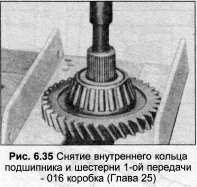
2. Clamp the output shaft in a vice on the visible part between the 3rd and 4th gears.

3. Using an extractor, remove the inner bearing ring from the pinion gear.

4. Remove the 1st gear needle bearing.

5. Remove the 1st gear synchronizer ring and install it on the gear.

6. Remove the retaining ring located opposite the synchronizer hub.

7. Insert the extractor with your feet under the 2nd gear, remove it with the 1/2 gear synchronizer assembly.

8. Lift the needle assembly of the 2nd gear, install it inside the gear.

9. The 3rd and 4th gears are pressed onto the shaft and if they need to be removed or the bearing at the end of the gears needs to be replaced, see your Audi dealer.

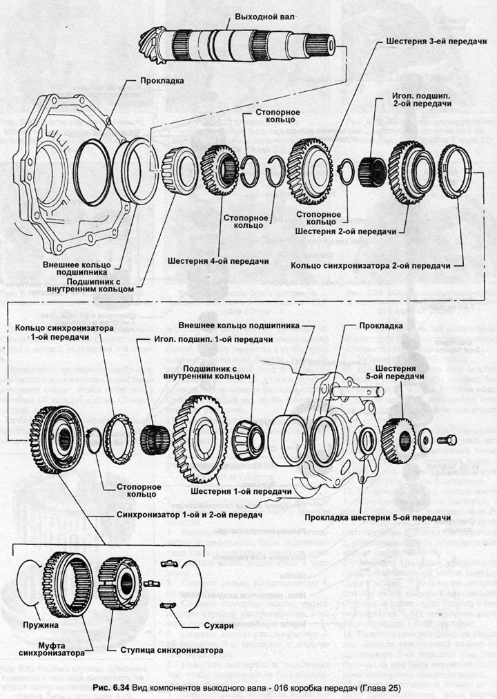
10. Begin assembly with the large inner bearing race, 4th gear, snap ring, 3rd gear and snap ring on the shaft as follows.

11. Lubricate the needle bearing of the 2nd gear with transmission oil, install it on the shaft.

12. Install the 2nd gear on the bearing, then place the synchronizer ring on the gear. Measure the gap shown in Fig. 6.5. If the gap exceeds the value given in the Specifications, install a new synchronizer ring.

13. If the synchronizer assembly has been disassembled, it must be assembled in the following way. Install three locking crackers into the grooves in the hub, secure them with retaining rings. The retaining rings must be located at 120°, the end of the retaining ring must enter the locking cracker. Put the sleeve on the synchronizer hub.


14. Install the synchronizer assembly onto the shaft, with the end of the sleeve with the teeth facing the gear. Before fully installing the hub, rotate the 2nd gear synchronizer ring so that the grooves in it are aligned with the locking crackers in the synchronizer assembly.

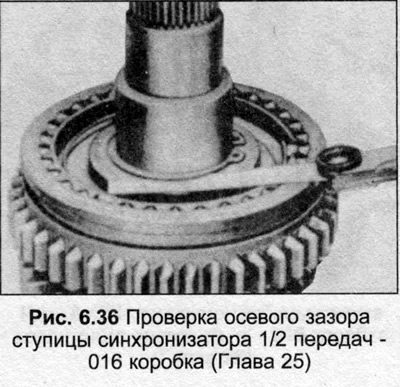
15. Install the retaining ring against the synchronizer hub and, pressing the hub as much as possible, measure the gap between the hub and the retaining ring (Fig. 6.36). The gap should be 0-0.04 mm and preferably closer to the lower value. If the gap exceeds the upper limit, install a new retaining ring of suitable thickness. Thicknesses can be 1.50, 1.55 and 1.60 mm.

15. Install the retaining ring against the synchronizer hub and, pressing the hub as much as…


16. Install the 1st gear synchronizer ring, aligning the grooves with the locking crackers in the synchronizer assembly.

17. Lubricate the needle bearing of the 1st gear with transmission oil, install it on the shaft, then install the 1st gear.

18. Measure the distance between the teeth on the synchronizer locking ring and the timing teeth on the gear as described in step 12 and install a new synchronizer ring if the gap exceeds 0.5 mm.

19. Place the inner bearing ring onto the end of the shaft.


19. Place the inner bearing ring onto the end of the shaft.


19. Place the inner bearing ring onto the end of the shaft.
The article was checked by auto expert Nikita Rudakov
This article is available at russian, bulgarian, belarusian, ukrainian, serbian, croatian, romanian, polish, slovak, hungarian

Share information:
Previous articles
Audi 100 C3: Mechanical gearbox
Next articles

Input shaft (016) — disassembly and assembly
Gearbox (016) — disassembly into main blocks
Gear shift rod (013 and 093) — disassembly and assembly
Gear Shift Lever (013 and 093) — Removal, Installation and…
Bearing/Gear Fastener (016) — Service
Gearbox/Final Drive Housing — Service (016)
Gear Fastener Housing Coating (016) — Maintenance
5th Gear Parts (016) — Maintenance


Similar articles on other Audi car models:
Disassembly and assembly of the primary shaft Audi 80 B2 (1979-1986)
Clutch and Drive Shaft Specifications Audi A3 Type 8L (1996-2003)
Cylinder head — disassembly, cleaning, inspection and assembly Audi A4 B5 (1994-2001)
Disassembly and assembly of the drive shaft Audi A6 C5 (1997-2004)
Disassembly and assembly of the shock absorber strut Audi A8 D2 (1994-2002)
Disassembly and assembly of the engine Audi Q5 Type 8R (2008-2017)
Disassembly and assembly of the gearshift mechanism drive Audi A2 (1999-2005)
Link to this page in different formats


Visitor comments

No comments yet


How much will 26 + 45 =


100(C4, 1990-1994) 
  • General information
  • User manual
  • Power unit
  • Engine repair
  • Ignition system
  • Fuel system (gasoline)
  • Fuel system (diesel)
  • Lubrication system
  • Cooling system
  • Exhaust system
  • Transmission
  • Clutch
  • Car gearbox
  • Drive shafts
  • Chassis
  • Car suspension
  • Steering
  • Wheels and tires
  • Brake system
  • Body
  • Ventilation and heating
  • Body repair
  • Electrical equipment
  • Power devices
  • Lighting and appliances
  • Electrical circuits
 
100(C4, 1990-1994, petrol) 
  • General information
  • Operation and maintenance
  • Power unit
  • Engine repair
  • Exhaust system
  • Cooling system
  • Supply system
  • Air filter
  • Mono-Motronic injection system
  • Digifant injection system
  • KE-III-Jetronic and KE-Motronic
  • MPI and MPFI injection system
  • Transmission
  • Clutch
  • Car gearbox
  • Chassis
  • Suspension and steering
  • Brake system
  • Wheels and tires
  • Body
  • Exterior
  • Interior
  • Electrical equipment
  • Fuses and relays
  • Power devices
  • Ignition system
  • Lighting and signaling
  • Equipment and devices
  • Electrical circuits
 
100(C3, 1982-1990) 
  • General information
  • User manual
  • Maintenance
  • Specifications
  • Power unit
  • Engines 4-cylinder
  • Engines 5-cylinder
  • Diesel engine
  • Cooling system
  • Power system (carburetor)
  • Power system (injector)
  • Fuel system (diesel)
  • Transistor ignition system
  • Electronic ignition system
  • Transmission
  • Clutch
  • 4 speed gearbox 014
  • 5 speed gearbox 013 and 093
  • 5 speed gearbox 016 and 012
  • Shift mechanism KP 016
  • Automatic transmission
  • Front wheel drive
  • Chassis
  • Front suspension
  • Rear suspension
  • Steering
  • Brake system
  • Body
  • Body elements
  • Electrical equipment
  • Lighting and appliances
  • Power devices
  • Electrical circuits
 
100(C3, 1982-1990, petrol) 
  • General information
  • Maintenance and operation
  • 4 cylinder engine
  • Engine repair
  • Cooling and lubrication system
  • Supply system
  • Ignition system
  • 5 cylinder engine
  • Engine repair
  • Cooling and lubrication system
  • Supply system
  • Ignition system
  • Transmission
  • Clutch and drive shafts
  • 4 speed gearbox 014
  • 5 speed gearbox 013 and 093
  • 5 speed gearbox 016 and 012
  • Automatic gearbox
  • Chassis
  • Steering
  • Front suspension
  • Rear suspension
  • Brake system
  • Body
  • Body elements
  • Doors, locks and windows
  • Body repair
  • Electrical equipment
  • Equipment and devices
  • Power devices
  • Electrical circuits
 
100(C3, 1982-1990, diesel) 
  • General information
  • User manual
  • Maintenance
  • Troubleshooting
  • Power unit
  • Engine in a car
  • Engine removed
  • Cooling system
  • Fuel system
  • Exhaust system
  • Starting and charging
  • Preheating
  • Transmission
  • Clutch
  • Mechanical gearbox
  • Automatic gearbox
  • Drive shafts
  • Chassis
  • Brake system
  • Suspension
  • Steering
  • Body
  • Exterior
  • Interior
  • Electrical equipment
  • Equipment and devices
  • Electrical circuits
 
AudiManual.ru © 2017-2026 · Mobile version · Feedback · Sitemap: EN BG BY UA RS HR RO PL SK HU · Site search · News and articles
80 B2 · 80 B3 petrol · 80 B3 · 80 B4 · 100 C3 diesel · 100 C3 petrol · 100 C3 · 100 C4 petrol · 100 C4 · A3 Type 8L · A4 B5 petrol · A4 B5 · A4 B6 petrol · A4 B6 · A4 B7 · A4 B8 · A6 C4 · A6 C5 · A6 C5 Allroad · A8 D2 · Q5 Type 8R · Q7 Typ 4L · Audi A2 ·
This site uses cookies 🍪. Click the button to accept this fact.