



Table of contents: Throttle valve ↓ Fuel mixture corrector ↓ Pressure in the system ↓ Pressure sensor ↓ Inlet nozzles ↓ Control unit ↓ Idle speed control valve ↓ Fuel starter valve ↓ Angular displacement sensor ↓ Fuel supply cut off (forced idle) ↓
To better understand the full functioning of our injection system, it is first necessary to clarify the most important details and concepts.
Throttle valve
There are two throttle valves in the intake manifold. The smaller of these valves is connected by a cable to the gas pedal in the passenger compartment. It controls the flow of intake air into the engine. If the accelerator pedal is pressed harder, the rod opens the second, larger valve. In the full "gas" position, both valves are open.
Fuel mixture corrector
It is the main component of the injection system and consists of an air flow meter and a fuel dispenser. They operate as follows:
The light tin disk of the air flow meter is located in the middle of the air flow sucked in by the engine. This valve shutter is lifted by the suction of the pistons during the intake stroke, and the more the more air passes from the throttle valve. The deflection of the disk is transmitted to the fuel metering device via a system of levers.
The fuel metering device consists mainly of a distribution piston and a valve housing. For each engine cylinder, there is a slot in the valve housing through which the fuel enters the corresponding injection nozzle. The distribution piston opens or closes these slots more or less and thus - depending on the position of the valve shutter - lets in the corresponding amount of fuel.
Pressure in the system
The fuel pump in the fuel tank pumps fuel under pressure into the injection system. The first instance here is the system pressure regulator in a separate housing. It reduces the increased pressure and leaves only 6.1 to 6.5 bar for the fuel system. This pressure, the system pressure, acts in the dispenser, fuel line and injection nozzles.
Pressure sensor
The pressure regulator is responsible for the mixture composition. This happens as follows: fuel supply to the lower chambers (through which you can influence the amount of the mixture) occurs through the pressure regulator. If it lets a lot of fuel into the lower chambers, then the pressure in the lower chambers increases. Consequence: the membranes of the so-called pressure drop valves bend towards the valve openings - less fuel gets to the injection nozzles. Vice versa, of course, it works in the same way. The desired result is achieved: the amount of fuel changes in relation to the incoming air - the mixture is enriched or depleted. The pressure regulator receives commands from the control unit. This occurs depending on the lambda regulation, engine temperature and load on it. The pressure sensor is located on the side of the fuel mixture regulator. Its functions should be considered in addition to the main function of the fuel mixture regulator, which is preserved in the event of electronic failure.
Inlet nozzles
Once the fuel pressure reaches 3.7-4.8 bar, the injectors feed gasoline into the channel in front of the valve of the corresponding cylinder. At the same time, they open up to 2000 times per second, due to which the gasoline is sprayed especially finely.
Control unit
The control unit regulates the engine mixture composition via the pressure regulator. In order for this control to be based on something, the control unit receives data on engine temperature, rotation speed, starting processes, valve shutter position (from idle to full load). The lambda probe signal, data from the ignition system, and atmospheric pressure sensor are added here (only for KE-lll-Jetronic) and from an automatic transmission. The control unit is located in the passenger compartment in the front passenger footwell.
Idle speed control valve
Function: the valve opens the air channel bypassing the throttle valve. The effect is as follows: due to the increased amount of air, the air flow meter "believes" that the throttle valve has opened slightly and therefore provides a correspondingly increased fuel supply. Desired result: increased rotation speed.
The amount of additional air supplied is determined by the KE-Motronic or KE-III-Jetronic injection system control unit, namely in accordance with the rotation speed at a given moment in time. In this way, the electronics strive to return the rotation speed to the standard range.
Fuel starter valve
This is an electromagnetically driven injector which, depending on the engine temperature at start-up, supplies an additional amount of finely atomized fuel to the intake manifold. The injection duration is determined by the KE-Motronic or KE-III-Jetronic injection system control unit.
Angular displacement sensor
The Audi-100 has two throttle angle sensors. They signal the following data:
Idle: to regulate the idle speed, stop the fuel supply in the forced idle mode; fully electronic ignition system, etc.
Full throttle: to enrich the fuel mixture in full throttle mode and fully electronic ignition system.
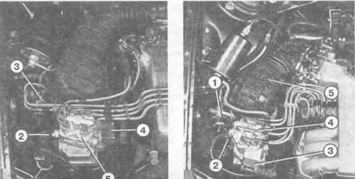
Left: KE-III-Jetronic injection system of a 4-cylinder engine:
1 - electromagnetic valve of the activated carbon tank;
2 - valve gate potentiometer;
3 - pressure regulator;
4 - pressure sensor;
5 — fuel dispenser.
Right: KE-Motronic injection system of a 5-cylinder engine:
1 - pressure regulator;
2 - valve gate potentiometer;
3 - pressure sensor;
4 — fuel dispenser;
5 — air intake sleeve.
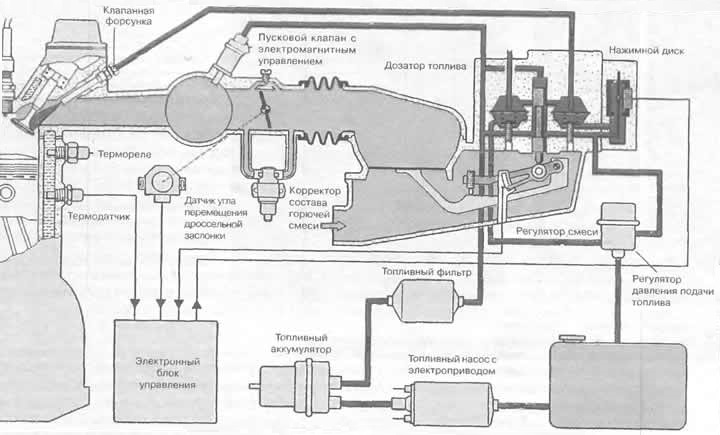
The operation diagram of the KE-III-Jetronic or KE-Motronic injection system. Fuel is shown in red, incoming air is highlighted in light pink.
Fuel supply cut off (forced idle)
The already mentioned pressure regulator stops the fuel supply if the car is operated in the forced idle mode. The control unit recognizes this mode by the information "the rotation speed is higher than the rotation speed in the idle mode" and "the throttle valve is closed".
(Material republished from the website: «AudiManual.ru»)