



Table of contents: Separating the exhaust pipe from the… ↓ Separating the exhaust pipe from the… ↓ Removal the lambda probe ↓ Weakening of the triangular flange ↓ Removal the clamp bracket ↓ Disassembling the exhaust system ↓ Separation of the main and… ↓
Below is a description of how to separate the individual components of the exhaust system. For reinstallation, the last section on assembling the exhaust system is important.
Note: To make it easier to remove the bolts when working on the exhaust system, the threads must be lubricated with graphite grease. The clamping sleeves also come off the pipe more easily if their inner side is treated with graphite grease.
Separating the exhaust pipe from the exhaust manifold
The spacer bolts that hold the exhaust pipe mounting nuts on them are easily broken if you try to remove a heavily rusted nut without first treating it.
Therefore, before work, you should treat the connection nuts with a rust removal spray or (often even better):
Cut off the nuts with a sharp chisel. They are usually made of a very soft material with a threaded part embedded in it. The threaded part will then need to be separately "picked off" from the thread of the spacer bolt.
Separating the exhaust pipe from the exhaust manifold
The new nuts from the "exhaust system mounting kit" also consist of this "soft" material. So do not use any other nuts from your home collection.
Tightening torque: 30 Nm.
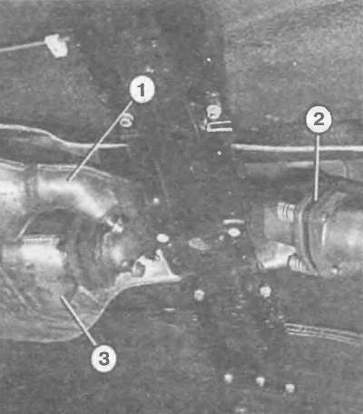
In the 6-cylinder engine of all-wheel drive vehicles, the right catalytic converter (3) is attached to the left one (1) by means of a triangular flange without a spring. The rigidity of the connection is achieved by means of a metal sealing ring. It is necessary to ensure that the flange cheeks are parallel to each other. Only such a triangular flange (2) is provided with springs in order to allow only a small movement of the exhaust system. Here, too, a metal sealing ring is installed.
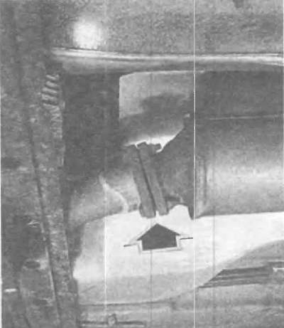
In cars with a 4-cylinder engine, the triangular flange connection (arrow) is also rigid. And here you should pay attention to the sealing ring, the flanges should also be located parallel to EACH other.
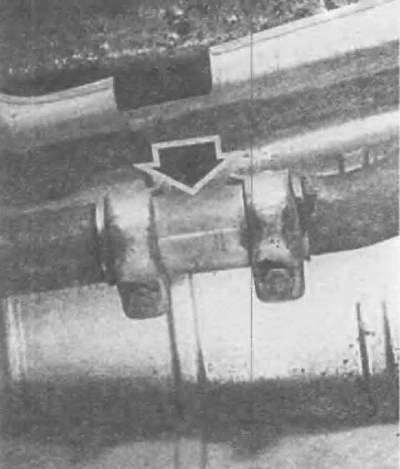
The double pipe clamp is replaced after one single bolt connection has become loose.
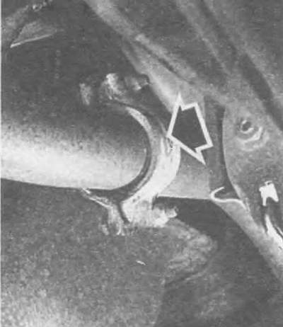
When installing the clamp bracket (arrow), ensure that it is installed correctly (horizontally and vertically).
Removal the lambda probe
Lambda (oxygen)- the probe must be removed when replacing the catalytic converter (or the probe itself).
Hang the wire fasteners from the body, separate the plug connections (view the entire length of the wire).
Unscrew the probe.
When installing the lambda probe, lubricate it with G 5 lubricant from the Audi workshop kit. However, the lubricant should not get into the slot of the probe housing.
Tightening torque: 50 Nm.
Weakening of the triangular flange
The double pipe clamp perfectly connects two pipe sections to each other, while allowing them to be easily separated. Important: the double pipe clamp cannot be used a second time. It must be replaced after only one bolt connection has become loose.
Note the position of the bracket for subsequent installation.
Loosen the connections on the double pipe clamp; before doing this, treat the threads with a rust remover.
If it is still impossible to separate the connection, then the bolt/nut must be separated using a cutting machine.
Another option is to cut off the nut with a chisel.
Tensioning torque for connections: 25 Nm.
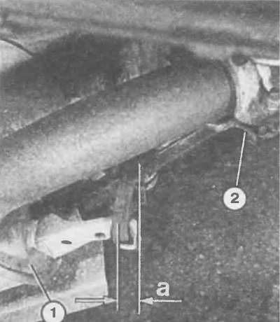
On front wheel drive models, the rear main muffler hanger pre-tension should be approximately 7 mm (with a cold exhaust system). The number "2" indicates the clamping bracket.
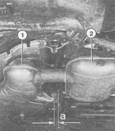
On 4WD models, the front main muffler retaining loop should be pre-tightened to approximately 7 mm (with a cold exhaust system). The number "2" indicates the rear center muffler.
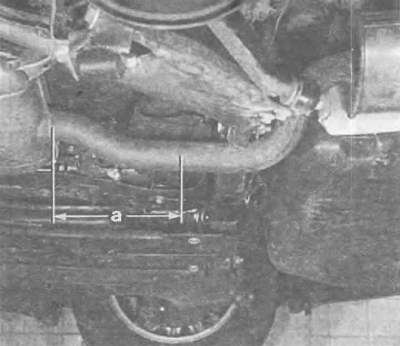
The section a = 291 mm marks the area where the main and additional mufflers of the exhaust system in all-wheel drive models must be separated from each other.
Removal the clamp bracket
Before you begin removing the clamp, you should remember exactly where it is installed: where do the bolt heads point? Is the clamp horizontal or vertical?
Watch the sealing gasket - it should not fall on the floor. The hard material can burst.
When installing, make sure that the halves of the bracket cover the protrusions at the ends of the pipe well.
Observe the installation position and tighten the connections to a torque of 25 Nm.
Disassembling the exhaust system
An exhaust system that is too tight during assembly can cause an annoying growling noise. Therefore:
Before tightening the screws, hang the exhaust system freely in the retaining loops and align it.
All parts must have sufficient free movement between their position and the body.
The tip should have the same distance from the cutout in the bumper everywhere.
The gearbox mount can be easily tightened to 25 Nm. Pay attention to the correct assembly of the sleeves and springs.
Pre-tightening the exhaust system to compensate for deformations at elevated temperatures:
On front wheel drive models the mounting loop at the rear of the main muffler should have 7mm of pre-tightening (illustration on the next page top left).
On 4WD models, the front main muffler retaining loop should be pre-tightened to approximately 7 mm (illustration on the next page top right).
Additionally, check on the 4WD model with a 6-cylinder engine: the retaining loop of the additional muffler should have 12-14 mm of pre-tightening.
The safety lugs of the fastening rings - these are the protruding ends of the fasteners - are turned approximately 90°. Make sure that the fastening ring is not pinched in the process.
Finally, tighten all exhaust system screws starting from the front. Initial tightening torque - see previous sections.
Separation of the main and additional mufflers (all-wheel drive models only)
In the case of the original exhaust system of the all-wheel drive Audi models, both mufflers are connected to each other by a single piece of pipe.
To replace just one muffler, this pipe must be sawed through.
To ensure there is no doubt as to where exactly to saw, the illustration below shows a section a = 291 mm.
Cut the pipe with a cutting machine, if possible, at an angle to the right.
Due to the lack of space under the car, it is almost impossible to saw with the mufflers still installed. It is better to remove both mufflers together.
Even if you need to replace both mufflers, you will receive both mufflers separately as spare parts.
In this case, they will be connected with a double pipe clamp (also purchased as a spare part) — as already described above.
Bolt tightening torque: 25 Nm.