
Table of contents: Instrument lighting ↓ Heater panel illumination ↓ Ashtray light ↓ Cigarette lighter illumination ↓ Glove box illumination ↓ Automatic transmission mode… ↓
Instrument lighting
Only the instrument lighting is considered here. You will read about the indicators, also located in the instrument cluster, in the chapter "Instruments and auxiliary devices". Removing the lighting devices:
Remove the steering wheel (chapter "Wheel suspension and steering").
Remove the instrument cluster unit (chapter "Instruments and auxiliary devices").
At the rear of the instrument cluster, the lamp sockets for the instrument lighting become accessible after folding back the rear housing cover (unscrew 2 TORX screws for this).
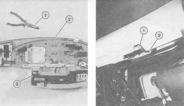
Left: Loosen the two TORX screws on the upper edge of the instrument panel. Now remove the rear cover (3) from the combined instrument (2). It is best to turn the bulbs in the combined instrument to the left together with the sockets by 90° using small pliers (1).
Right: The socket and contact switch for the glove compartment light are combined and are located on the upper edge of the glove compartment recess. The bulb (1) is released from the socket after turning to the left. The contact switch is actuated by the glove compartment hinge bracket (2).
Lamps with a glass base form a single unit with the socket.
Insert the bulb holder back into the instrument cluster and turn it to the right until it stops.
Turn the cartridges and remove them.
Heater panel illumination
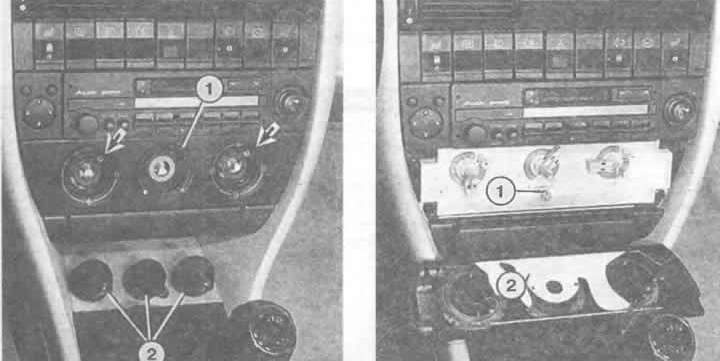
Remove the handles of the three rotary controls of the heating and ventilation system.
Remove the two Phillips head screws below and remove the panel.
Now you can see the light bulbs with glass bases.
Remove the light bulbs from the sockets.
Ashtray light
Remove the handles of the three rotary controls of the heating and ventilation system.
Remove the two Phillips head screws below and remove the panel.
Unscrew one small screw on the right and left corners at the top of the ashtray.
Remove the ashtray downwards.
Remove the bulb holder from the rear of the ashtray housing.
Replace the lamp.
Cigarette lighter illumination
Cigarette lighter front: remove all three rotary control knobs of the heating and ventilation system.
Remove the two Phillips head screws below and remove the panel.
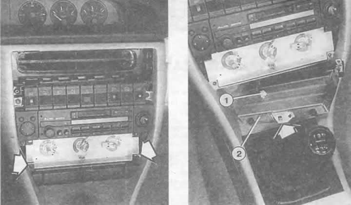
There are two screws located directly under the cigarette lighter - unscrew the right one.
Press the cigarette lighter together with the built-in panel down a little and remove it.
Raise the mounting bar (earring) and remove the socket with the lamp.
Cigarette lighter rear: "Floor covering" rear in center console (protruding part of the floor between the front seats) remove and pull forward a little.
Remove the Phillips head screw underneath.
Remove the panel around the rear cigarette lighter using a narrow screwdriver.
There are 2 Phillips head screws underneath it - unscrew them.
Replacing the heating switch lighting.
Left: Remove all controls (2). Unscrew the Phillips-head screws indicated by the arrows. Remove the panel (1).
Right: With the switch cover (2) removed, the glass-base bulb (1) underneath the heat regulator is accessible. The bulb is easily removed.
Left: Removing the ashtray lighting. After performing the operation described on the previous page, the screws (arrows) located under the heating control panel become accessible.
Right: On the back of the ashtray body is the lamp for its illumination. It is simply inserted into the holder.
Remove the cigarette lighter back from the center console together with the nozzle.
Lift the small mounting panel and remove the socket with the bulb from the cigarette lighter.
Glove box illumination
The glove compartment light contains a contact switch in one housing. Power is supplied only when the side lights or headlights are on.
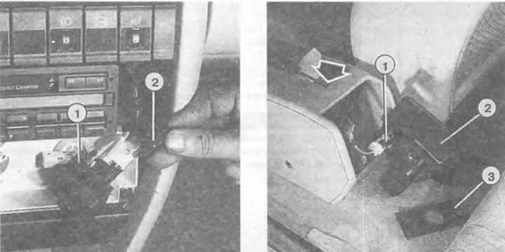
On the back of the glove box, turn the 4-watt incandescent light bulb to the left (you need to rebuild your view: the lamp points forward as you go) and pull it up (bayonet locking device).
To remove the entire unit, disconnect the plugs and push the cartridge out of the mount towards the passenger compartment.
Automatic transmission mode indicator backlight
A lamp with a glass base is used to illuminate the automatic transmission mode indicator on the selector lever when the ignition is on (1.2W, DIN-form W).
Remove the center console, see chapter "Salon".
Disconnect the bulb socket from the automatic transmission selector lever console.
Remove the glass-base light bulb from the socket.
Almost all switches have symbol backlighting, but only a few of them have a replacement backlight bulb. If the switch burns out, pay attention to it or replace it.
There is no rule without exception: some of the switches above the radio have replaceable bulbs (see chapter "Instruments and auxiliary devices").
Left: The front cigarette lighter socket (2) can be removed if the cigarette lighter (1) is removed by loosening the screw and pressing the cigarette lighter down slightly. The mounting screw is accessible after removing the heating switch panel (pictures on the opposite page).
Right: Removing the rear cigarette lighter lighting. Legend:
1 — cigarette lighter lamp socket;
2 - air nozzle;
3 — panel.
The arrow points to the position where, when the cover is folded back, the Phillips-head screw is located, which must be unscrewed.
The original article is located on the online resource: audimanual