
Differential
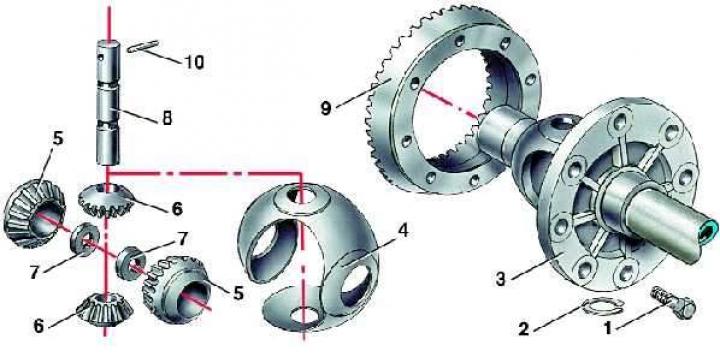
- 1 - bolt;
- 2 - spring washer;
- 3 - differential box;
- 4 - separator;
- 5 - axle gear;
- 6 - satellite gear;
- 7 - nut;
- 8 - axis;
- 9 - driven gear;
- 10 - stopper
Installing the speedometer drive pinion
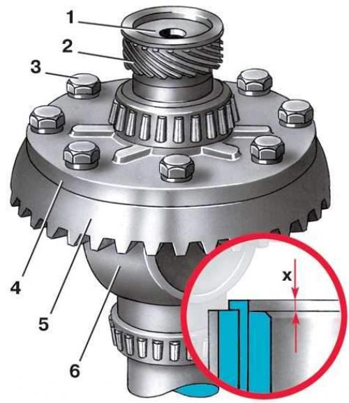
- 1 - bushing;
- 2 - speedometer drive pinion;
- 3 - bolt;
- 4 - differential box flange;
- 5 - driven gear of the main transmission;
- 6 - differential box;
- X - bushing protrusion
Disassembly
1. Press out the drive gear 2 (see Fig. Installing the speedometer drive pinion) speedometer drive from the differential box.
2. Press the differential bearings. It is recommended to mark them relative to which side they were.
3. Mark the relative positions of the driven gear and the differential box flange. Unscrew the eight bolts 1 (see Fig. Differential) fasteners and press the driven gear 9 of the main gear from the differential box 3.
4. Using a thin, hard rod, knock out the stopper 10 of the satellite axle from the differential box hole. Knock out the satellite axle from the box.
5. Remove the satellites by rolling them out, and then remove the axle gears with round nuts.
6. Remove separator 4.
Assembly
1. Install separator 4 into differential box 3.
2. Install axle gears 5 with round nuts 7.
3. Insert the satellites into the box windows, engaging them with the axle gears. Temporarily insert both axle flanges and turn them so that the holes for the axle on the differential box and the satellites align.
4. Insert the 8 satellite axle, aligning the holes in the box and the axle under the stopper. Fix the satellite axle with stopper 10.
5. Heat the driven gear to a temperature of 100°C and press it onto the differential box 3. To do this, you can use the two bolts 1 for its fastening.
6. Allow the gear to cool and tighten all its mounting bolts 1 to a torque of 55 N·m (5.5 kgf·m).
7. Heat the inner rings of the differential bearings to a temperature of 100°C and press them onto the differential case.
8. Install drive gear 2 (see Fig. Installing the speedometer drive pinion) speedometer drive and press on bushing 1 of the drive, ensuring its protrusion by 1.4 mm by selecting adjusting rings with a thickness of 1.4 to 1.5 mm.