
Gear shift control mechanism of the 014 type gearbox
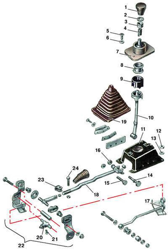
- 1 - handle;
- 2 - retaining ring;
- 3 - washer;
- 4 - spring;
- 5 - bolt;
- 6 - washer;
- 7 - hinge housing;
- 8 - shell;
- 9 - rubber collar;
- 10 - gear shift lever;
- 11 - body;
- 12 - nut;
- 13 - washer;
- 14, 15 - bolts;
- 16 - nut;
- 17 - jet thrust;
- 18 - gear shift rod;
- 19 - case;
- 20 - coupling;
- 21 - screw;
- 22 - wings;
- 23 - terminal;
- 24 - bolt
Gear shift lever and gearbox rod type 014
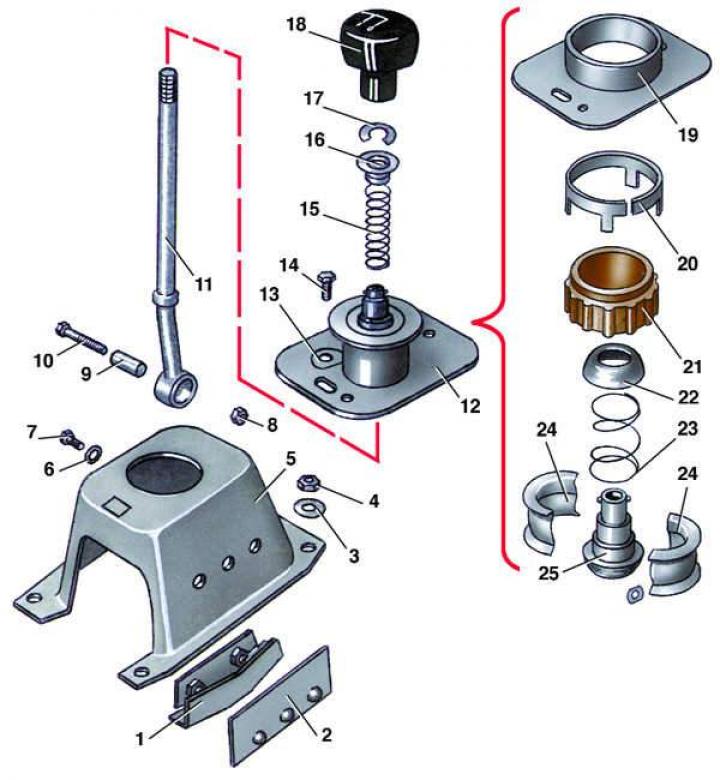
- 1 - reverse gear lock;
- 2 - thrust plate;
- 3 - washer;
- 4 - nut;
- 5 - body;
- 6 - washer;
- 7 - bolt;
- 8 - nut;
- 9 - bushing;
- 10 - bolt;
- 11 - gear shift lever;
- 12 - hinge assembly;
- 13 - washer;
- 14 - bolt;
- 15 - spring;
- 16 - spring cup;
- 17 - retaining ring;
- 18 - handle;
- 19 - hinge housing;
- 20 - retaining ring;
- 21 - rubber collar;
- 22 - upper hemisphere;
- 23 - spring;
- 24 - shell;
- 25 - lower hemisphere
Removal
1. Mark the position of the rod 18 in the axial and angular directions (see Fig. Gear shift control mechanism of the 014 type gearbox) shift gears in the terminal connection, then unscrew the terminal connection bolt.
2. Remove the center console (see pp. 1–8 or paragraphs 10–15 of subsection 11.23).
3. Unscrew nuts 4 (see fig. Gear shift lever and gearbox rod type 014) and remove washers 3.
4. Remove housing 5 together with the gear shift lever assembly.
5. Unscrew nut 8, remove bolt 10 and remove the gear shift rod.
Disassembly
1. Unscrew handle 18 (see Fig. Gear shift lever and gearbox rod type 014) gear shift lever.
2. Remove retaining ring 17 and spring 15 with cup 16.
3. Remove gear shift lever 11 from hinge 12.
4. Mark the relative positions of the hinge housing 19 and housing 5 and unscrew the two bolts 14.
5. Remove joint 12 as an assembly from housing 5.
6. Move the rubber collar 21 and the retaining ring 20 downwards.
7. Move apart the two halves of the shell 24 in the rubber collar 21 and remove the hemispheres 22 and 25 with the spring 23.
8. Remove the shell halves 24 from the rubber collar 21.
Assembly
1. Insert into rubber collar 21 (see fig. Gear shift lever and gearbox rod type 014) two halves of the shell 24.
2. Having moved apart the shells 24, insert the assembled lower 25 and upper 22 hemispheres with spring 23.
3. Insert the assembled hinge into the housing 19 and secure it with ring 20.
4. Insert gear shift lever 11 into joint 12.
5. Install ball joint 12 with gear shift lever assembly on housing 5 according to previously made marks and tighten bolts 14.
Installation
Install the gear shift lever in reverse order.