
Table of contents: Gearboxes 01N and 097 ↓ Gearbox Locking Cable 097 ↓
Gear Shift Lever 01N
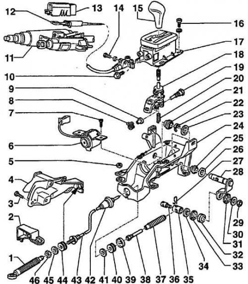
- 1. Rubber cover
- 2. Retainer
- 3. Bolt
- 4. Support bracket
- 5. Nut
- 6. Shift lever locking valve
- 7. Bolt
- 8. Spring
- 9. Bushing
- 10. Bolt
- 11. Ignition switch
- 12. Locking cable
- 13. Lid
- 14. Bolt
- 15. Handle
- 16. Bolt
- 17. Lever casing
- 18. Gear shift lever
- 19. Pin
- 20. Spring
- 21. Bushing
- 22. Retaining ring
- 23. Washer
- 24. Bracket
- 25. Bushing
- 26. Spring clamp
- 28. Lever
- 29. Nut
- 30. Washer
- 31. Ring
- 32. Bushing
- 33. Ring
- 34. Washer
- 35. Sleeve
- 36. Pin
- 37. Rubber cover
- 38. Nut and guide tube
- 39. Washer
- 40. Bushing
- 41. Washer
- 42. Sealing ring
- 43. Cable
- 44. Bushing
- 45. Washer
- 46. Nut
On 097 models, a locking cable connects the gearshift lever and the ignition switch.
Gearboxes 01N and 097
Removal
1. Place the gear shift lever in neutral position.
2. Raise and support the front of the vehicle.
3. Remove the heat shield from the gear shift bracket.
4. Disconnect the gear shift cable from the transmission.
5. On 01N models, remove the nut and bolt at the rear of the right transmission mount.
6. Remove the right transmission support bracket.
7. On 01N models produced before June 1995, remove the clip and press the bushing out of the shift lever base.
8. Remove the center console.
9. Remove the gear shift lever mechanism.
10. Loosen the lock nut and disconnect the inner cable.
11. Slide the rubber boot back and remove the nut and guide tube from the cable.
12. Disconnect the cable from the rear cover of the shift lever mechanism.
Installation
Installation is carried out in the reverse order of removal.
Adjustment
1. Place the gear shift lever in the park (P) position.
2. Place the gearshift lever on the transmission in the park position.
3. Make sure the cable is not twisted or compressed. Tighten the clamp nut.
4. Check the operation of the gear shift lever.
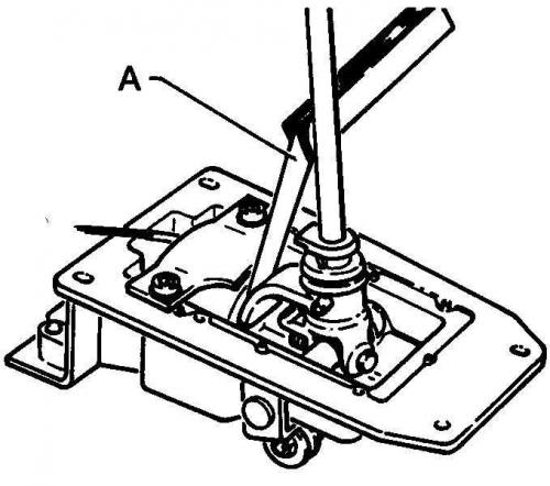
5. Set the lever to position (R), check with a feeler gauge that the gap between the locking solenoid valve and the lever is within 0.6 - 1.4 mm (A). Adjust the valve position if necessary.
Gearbox Locking Cable 097
Removal
1. Remove the center console.
2. Remove the steering wheel and instrument panel.
3. Place the gearshift lever in position (N).
4. Remove the bolt securing the cable to the lever mechanism.
5. Remove the ignition switch cover and disconnect the cable clamp.
6. Disconnect the cable from the ignition switch.
Installation
Installation is carried out in the reverse order of removal.
Adjustment
1. Turn on the ignition.
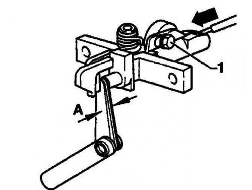
2. Loosen the adjusting bolt (1) and adjust the gap between the sash and the locking mechanism pin using a feeler gauge (A = 1.4–1.7 mm).
3. Check the operation of the mechanism.
(The original text of the material can be found on the website AUDImanual)