
Table of contents: Technical characteristics of AEL ↓ Technical specifications of CBU ↓ Automatic transmission cooling… ↓ Automatic transmission 097 –… ↓ Valve block ↓ Mechanical valve ↓ Oil filter installation position ↓ Parking gear lock ↓ Differential (automatic transmission) ↓ Drive gear ↓ Pinion gear ↓ Differential ↓
Technical characteristics of AEL
| Transmission: | ||
| Code designation |
AEL
| |
| Automatic transmission |
097
| |
| Torque converter: | ||
| Code designation |
LCCA
| |
| Valve block: | ||
| Code designation |
LAA
| |
| Number of spline rings |
int.
|
ext.
|
| – coupling K1 |
5
|
4
|
| – coupling K2 |
5
|
5
|
| – coupling K3 |
5
|
4
|
| – brake B1 |
6
|
6
|
| – brake B2 |
6
|
5
|
| Engine |
Volume 2.3 liters
| |
| Final drive ratio |
3.70
| |
| Gear ratio: | ||
| - 1st gear |
2.71
| |
| - 2nd gear |
1.55
| |
| - 3rd gear |
1.00
| |
| - 4th gear |
0.68
| |
| - reverse gear |
2.11
| |
| Automatic transmission fluid cooling radiator |
installed in the engine radiator
| |
Technical specifications of CBU
| Transmission: | ||
| Code designation |
CBU
| |
| Automatic transmission |
097
| |
| Torque converter: | ||
| Code designation |
LBCA
| |
| Valve block: | ||
| Code designation |
LAC
| |
| Number of spline rings |
int.
|
ext.
|
| – coupling K1 |
5
|
4
|
| – coupling K2 |
5
|
5
|
| – coupling K3 |
5
|
4
|
| – brake B1 |
6
|
6
|
| – brake B2 |
6
|
7
|
| Engine |
Volume 2.3 liters
| |
| Final drive ratio |
3.70
| |
| Gear ratio: | ||
| - 1st gear |
2.71
| |
| - 2nd gear |
1.55
| |
| - 3rd gear |
1.00
| |
| - 4th gear |
0.68
| |
| - reverse gear |
2.11
| |
| Automatic transmission fluid cooling radiator |
installed in the engine radiator
| |
The automatic transmission fluid cooling radiator is installed in the engine radiator
Automatic transmission cooling mechanism
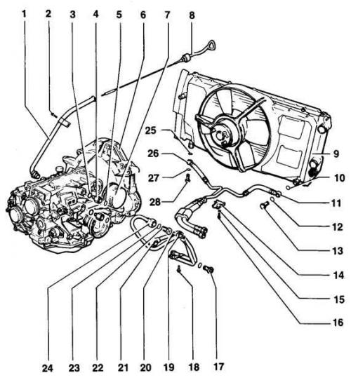
- 1. Feed hose
- 2. Bolt, 10 Nm
- 3. Sealing ring
- 4. Nut, tightening torque 60 Nm
- 5. Washer
- 6. Gearbox housing
- 7. Automatic transmission coolant filter
- 8. Dipstick for measuring the level of automatic transmission coolant
- 9. Radiator - with installed automatic transmission coolant radiator
- 10. Washer
- 11. Return line of the automatic transmission coolant radiator
- 12. Washer
- 13. Banjo bolt, 40 Nm
- 14. Clamp
- 15. Washer
- 16. Bolt, 10 Nm
- 17. Banjo bolt, 30 Nm
- 18. Bolt, 10 Nm
- 19. Temperature switch, 15 Nm
- 20. Washer
- 21. Automatic transmission fluid supply pipe
- 22. Banjo bolt, 30 Nm - with hole for temperature switch
- 23. Washer
- 24. Automatic transmission radiator coolant return pipe
- 25. Banjo bolt, 40 Nm
- 26. Sealing ring
- 27. Automatic transmission coolant radiator feed line
- 28. Washer
Warning: Tightening torque for fastening the supply hose 1 to the oil pan: 80 Nm
Warning: Always replace O-rings 3, 26.
Warning: Always replace washers 5, 10, 12, 20, 23, 28.
Warning: The automatic transmission coolant filter 7 can be replaced without removing the engine
Warning: Tightening torque of the return pipe of the automatic transmission coolant radiator return line: 40 N·m
Warning: Tightening torque for fastening the 21 automatic transmission fluid feed pipe to the feed line: 40 Nm
Warning: Tightening torque of the coolant return pipe 24 of the automatic transmission radiator to the return pipe: 40 Nm
Warning: Tightening torque of the fastening of the feed pipe of the coolant radiator pipe 27 automatic transmission: 40 N·m
Removal
1. Disconnect the negative battery cable.
2. Disconnect the speedometer connection connector.
3. Disconnect the temperature switch connection connector.
4. Remove the upper engine and gearbox mounting bolts.
5. Disconnect the oxygen sensor connection connector.
6. Disconnect the transmission ground wire.
7. Install the engine mount.
8. Remove the lower engine shield and mounts.
9. Remove the exhaust pipe.
10. Disconnect the axle shafts from the gearbox.
11. Remove the starter bolts.
12. Place the starter on its side and secure it with wire.
13. Remove the torque converter mounting nuts (3 pieces).
14. Remove the heat shield of the multifunction switch.
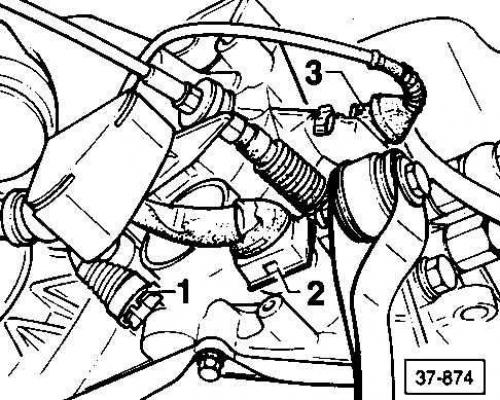
15. Disconnect connection connectors 1, 2 and 3.
16. Remove the wire clamp from the gearbox.
17. Disconnect the automatic transmission coolant pipes.
18. Seal the hoses using plugs, part number 357 853 586 B.
19. Seal the tubes with rubber caps, part 055 121 324.
Disclaimer: Part numbers are provided for reference purposes only.
20. Place a support or suitable lift under the transmission.
21. Remove the gearbox mounts.
22. Remove the shift lever clamp.
23. Disconnect the cable.
24. Remove the lower engine/transmission mounting bolts.
25. Move the axle shafts back.
26. Disconnect the gearbox from the engine.
27. Carefully lower the gearbox.
28. Support the torque converter to prevent it from falling.
Installation
1. Installation is carried out in the reverse order of removal.
2. Make sure the guide bushings are positioned accurately during installation.
3. Check the gear shift cable adjustment.
4. Adjust the cable if necessary.
Tightening torque
| Fastening the axle shafts to the drive flanges |
80 Nm
|
| Torque converter mounting bolts |
60 Nm
|
| Gearbox to engine mounting bolts (4-cylinder) |
55 Nm
|
| Gearbox to engine mounting bolts (5-cylinder) |
see table Tightening torques (5-cylinder engines)
|
| Fastening the gearbox bracket to the gearbox |
40 Nm
|
| Fastening the gearbox to the body |
110 Nm
|
Automatic transmission 097 – housing, gears, shafts/ Automatic transmission mechanism
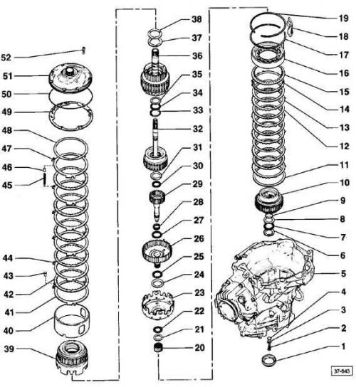
- 1. Lid
- 2. Bolt, 30 Nm - for small drive shaft
- 3. Washer
- 4. Washer - for planetary gear carrier
- 5. Gearbox housing
- 6. Washer
- 7. Thrust needle bearing
- 8. Washer
- 9. Sealing ring
- 10. Planetary gear carrier
- 11. Washer - for reverse gear brake (B1)
- 12. Internal spline ring
- 13. External spline ring
- 14. Pressure ring
- 15. Ring spring
- 16. One-way clutch - with piston B1
- 17. Retaining ring - for one-way coupling
- 18. Oil deflector
- 19. Retaining ring - for mounting rim
- 20. Central gear, small
- 21. Washer
- 22. Thrust needle bearing
- 23. Central gear, large
- 24. Washer
- 25. Thrust needle bearing
- 26. Drive shaft, large
- 27. Thrust needle bearing
- 28. Needle bearing
- 29. Drive shaft, small
- 30. Thrust needle bearing
- 31. Washer
- 32. 3rd/4th gear clutch (K3) - with pump shaft
- 33. Washer
- 34. Thrust needle bearing
- 35. Washer
- 36. Clutch 1st - 3rd gear (K1) - with turbine shaft
- 37. Washer - for adjusting the free travel of the K1 and K2 clutches (if necessary, a second washer is installed)
- 38. Washer - for adjusting the free travel of the K1 and K2 clutches (if necessary, a second washer is installed)
- 39. Reverse clutch (K2)
- 40. Mounting rim
- 41. External spline ring
- 42. Internal spline ring
- 43. Spring cap
- 44. External spline ring
- 45. Spring
- 46. Spring cap
- 47. External spline ring
- 48. Spring washer, concave
- 49. Gasket
- 50. Sealing ring
- 51. Automatic transmission coolant pump
- 52. Bolt, 10 Nm
Warning: Remove cover 1 using a screwdriver and install using a 40–20 bushing.
Warning: The tongues of washer 6 face the thrust needle bearing.
Warning: Always replace the sealing ring 9, installed on the planetary carrier
Caution: When installing, lightly grease the washers and needle bearing, install the washers and needle bearing on the planet carrier, and then install the planet rings
Warning: Before installing new 12 spline inner rings, soak them in automatic transmission fluid for 15 minutes.
Warning: The flat side of the pressure ring 14 faces the rings.
Warning: The curved side of the ring spring 15 faces the one-way clutch.
Warning: After installing the retaining ring 17, install the oil deflector 18.
Warning: Oil deflector 18 is installed in the groove of the gearbox housing (near the automatic transmission fluid vent), install the reflector after installing the one-way clutch and before installing the retaining ring.
Warning: Before installing the retaining ring 19, check that the one-way clutch and oil deflector are installed.
Warning: Central gears 20, 23 are installed on the planetary gear carrier.
Caution: Install washer 21 with the rounded side facing the small central gear.
Warning: Washer 24 is installed with the beveled side into the large central gear.
Warning: Drive shafts 26, 29 are installed on the planetary gear carrier.
Warning: The 30 thrust needle bearing faces the small drive shaft. The washer may be installed on the needle bearing.
Warning: The tongues of washer 31 face the thrust needle bearing, the washer can be installed on the needle bearing
Warning: The tongues of washer 33 face the thrust needle bearing.
Warning: The mounting rim 40 is installed so that the wedges of the one-way clutch enter the groove.
Warning: Always install the 41 mm thick outer spline ring.
Warning: Before installing new 42 mm internal spline rings, soak them in ATF for 15 minutes.
Warning: Remove all three spring caps 43, install after installing the first outer spline ring.
Warning: Always install the 44 mm thick outer spline ring.
Warning: Remove all three 45 springs, install after installing all outer spline rings.
Warning: Remove all three spring caps 46, install before installing the last outer spline ring.
Warning: Always replace gasket 49.
Warning: Always replace the sealing ring 50, installed on the automatic transmission coolant pump.
Pin Location
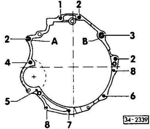
Warning: Before installing the motor, check that the pins are in place.
For some gearboxes installed on a 5-cylinder engine, it is necessary to install a deflection sleeve (detail 012 301 153).
When installing a new engine, check for the presence of a bushing on the crankshaft. This bushing should be installed first, before installing the drive plate.
Part numbers are provided for reference purposes only. Contact your dealer for the latest information.
Tightening torques (5-cylinder engines)
| Position | Bolt size | Quantity | Tightening torque (Nm) |
|
1
|
M12x67
|
1
|
65
|
|
2
|
M12x80
|
3
|
65
|
|
3
|
M12x90
|
1
|
65
|
|
4
|
M12x100
|
1
|
65
|
|
5
|
M12x120
|
1
|
65
|
|
6
|
M12x50
|
1
|
45
|
|
7
|
M12x38
|
1
|
45
|
|
8
|
M12x40
|
2
|
25
|
| Positions A and B – centering bushings | |||
Valve block
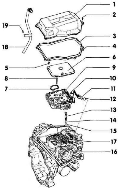
- 1. Oil pan
- 2. Bolt, 10 Nm
- 3. Gasket
- 4. Spacer
- 5. Oil filter
- 6. Valve block
- 7. Bolt, 10 Nm
- 8. Connection connector
- 9. Sealing ring
- 10. Plug
- 11. Sealing ring
- 12. Sealing ring
- 13. Mechanical valve transmitting rod
- 14. Main gear housing
- 15. Seal
- 16. Bolt, 5 Nm
- 17. Bolt, 8 Nm
- 18. Automatic transmission coolant radiator feed pipe
- 19. Bolt, 10 Nm
Warning: The valve block can be removed without removing the transmission from the vehicle. Replace the valve block if it is dirty or damaged.
Warning: Do not start the engine or tow the vehicle if the oil pan has been removed or there is no oil in the transmission.
Caution: Before removing oil pan 1, remove the coolant feed pipe.
Warning: Always replace gasket 3, install spacer on gasket.
Warning: Install spacer 4 on the gasket.
Warning: Install oil filter seal 5.
Warning: Connection connector 8 is installed together with a sealing ring.
Warning: Always replace O-rings 9, 11, 12.
Warning: Remove plug 10 before removing/installing the one-way clutch.
Warning: The flanged end of the mechanical valve transmission rod 13 must face the valve.
Warning: Always replace seal 15, installed in the oil filter.
Warning: Tightening torque for fastening the coolant radiator feed pipe 18 automatic transmission to the oil pan: 80 N·m
Identification
The code designation is embossed on a metal plate which must remain attached to the valve block.
Execution order
1. Install the sealing rings onto the plug.
Warning: Before removing/installing the one-way clutch, remove the plug from the crankcase to avoid damaging the plug and sealing ring.
2. Install the plug so that the rim is in the groove on the crankcase.
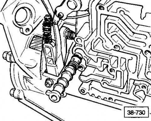
Mechanical valve
Installation
1. Move the gear shift lever to position P.
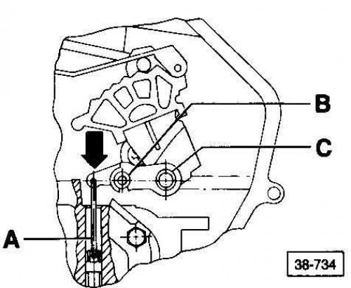
2. Install the mechanical valve all the way into the valve block. The transmitting rod A is indicated by the arrow.
3. Tighten limit screw B to 4 Nm
Warning: The lever C of the mechanical valve must be pressed against the limit screw B during installation. When tightening the screw B of the lever C of the mechanical valve, hold the lever by pressing it in the direction of the arrow.
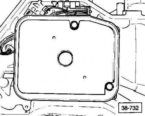
Oil filter installation position
Parking gear lock
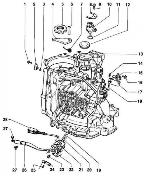
- 1. Bolt, 10 Nm
- 2. Plug
- 3. Sealing ring
- 4. Parking brake lock latch
- 5. Parking gear
- 6. Parking gear lock latch pin
- 7. Return spring
- 8. Lock - for multifunctional switch
- 9. Bolt, 10 Nm
- 10. Multi-function switch (F125)
- 11. Sealing ring
- 12. Cap
- 13. Main gear housing
- 14. Sealing ring
- 15. Speed sensor
- 16. Bolt, 10 Nm.
- 17. Gear shift shaft lever
- 18. Bolt, 10 Nm
- 19. Bushing
- 20. Sealing ring
- 21. Gear shift shaft
- 22. Locking washer
- 23. Bolt, 10 Nm
- 24. Mechanical valve lever
- 25. Bolt, 4 Nm
- 26. Locking spring
- 27. Bolt, 10 Nm
- 28. Lever
Warning: Always replace O-rings 3, 11, 14, 20.
Warning: Parking brake lock latch 4 is installed together with the return spring, align with the parking gear pinion.
Caution: The rounded side of the parking gear pinion 5 faces the drive gear cover.
Caution: Install the parking gear lock latch pin 6 using a drift.
Warning: Remove/install bushing 19 using a mandrel.
Warning: O-ring 20 is installed in the groove of the gearshift shaft.
Warning: Before removing the gear shift shaft 21, remove the multi-function switch and locking spring, always install together with the lever.
Differential (automatic transmission)
Warning: If you drop the speedometer drive during assembly, it may affect the accuracy of the speedometer readings in the future.
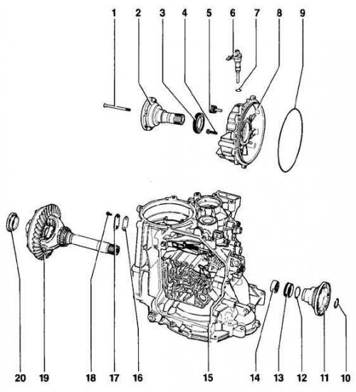
- 1. Bolt, 25 Nm
- 2. Left axle shaft flange
- 3. Axle shaft flange seal
- 4. Bolt, 25 Nm
- 5. Automatic transmission fluid filler plug
- 6. Speedometer drive
- 7. Sealing ring
- 8. Main gear cover
- 9. Seal
- 10. Axle shaft flange retaining ring
- 11. Half shaft flange
- 12. Sealing ring
- 13. Seal
- 14. Needle bearing
- 15. Gearbox housing
- 16. Gasket
- 17. Axle shaft ventilation cover
- 18. Bolt, 10 Nm
- 19. Differential
- 20. Pulse ring - for electronic speedometer
Warning: Do not use household detergents to avoid damaging the washer pump.
Warning: Always replace O-rings 7, 12.
Warning: When replacing final drive cover 8, adjust the ring gear installation.
Warning: Always replace oil seal 9.
Warning: Remove oil seal 13 using lever VW681.
Drive gear
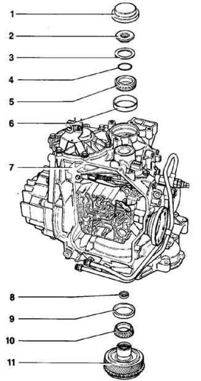
- 1. Rubber cover
- 2. Tension bolt, 250 Nm
- 3. Spherical washer
- 4. Washer
- 5. Inner race of tapered roller bearing
- 6. Outer race of tapered roller bearing
- 7. Gearbox housing
- 8. Thrust bearing
- 9. Outer race of tapered roller bearing
- 10. Inner race of tapered roller bearing
- 11. Drive gear
Warning: Remove rubber cover 1 with a screwdriver and install with a 40-20 bushing.
Warning: When removing/installing bolt 2, engage the parking gear.
Caution: The convex side of the spherical washer 3 faces the tension bolt.
Caution: Tapered roller bearing inner race 5: Install so that the tongues fit into the groove of the other tapered roller bearing inner race. After determining the required shim thickness, install the race onto the pinion gear after applying a coat of AMV 185 10001 sealant.
Warning: Tapered roller bearing outer race 6: Remove with a suitable drift, install with a 30-20 thrust block, apply a layer of AMV 185 10001 sealant.
Warning: The flat side of the thrust bearing 8 faces the drive shaft, install the tension bolt on the drive gear before installation.
Warning: Tapered roller bearing outer race 9: Remove using a suitable drift, install using a thrust block, apply a coat of AMV 185 10001 sealant.
Pinion gear
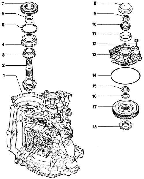
- 1. Gearbox housing
- 2. The drive gear is paired with the ring gear
- 3. Inner race of tapered roller bearing
- 4. Outer race of tapered roller bearing
- 5. Washer S3
- 6. Drive gear shaft sleeve
- 7. Pinion shaft seal
- 8. Rubber cover
- 9. Hexagonal nut
- 10. Inner race of tapered roller bearing
- 11. Outer race of tapered roller bearing
- 12. Bolt, 25 Nm
- 13. Drive gear cover
- 14. Sealing ring
- 15. Spacer sleeve
- 16. Washer S4
- 17. Drive pinion
- 18. Parking gear lock gear
Warning: Do not use household detergents to avoid damaging the washer pump.
Warning: Pinion 2 is paired with the ring gear and must be replaced together.
Caution: Tapered roller bearing outer race 4: Remove using a drift.
Warning: Pinion shaft sleeve 6: Remove together with the inner race of the tapered roller bearing.
Warning: Pinion shaft seal 7: Always replace, remove with a screwdriver.
Warning: Rubber cover 8: Remove with a screwdriver.
Caution: Tapered roller bearing outer race 11: Remove using a drift.
Warning: Always replace O-ring 14.
Warning: Spacer sleeve 15: The wider contact surface faces the drive gear.
Warning: Pinion drive 17: Higher edge faces parking gear lock latch.
Warning: Parking gear lock pinion 18: Rounded side faces drive pinion.
Differential
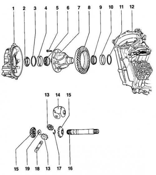
- 1. Differential cover
- 2. Impulse wheel
- 3. Washer S1
- 4. Outer race of tapered roller bearing
- 5. Bolt, 90 Nm
- 6. Inner race of tapered roller bearing
- 7. Differential box
- 8. Toothed crown - paired with the leading pinion
- 9. Inner race of tapered roller bearing
- 10. Outer race of tapered roller bearing
- 11. Washer S2
- 12. Gearbox housing
- 13. Satellites
- 14. Thrust washer
- 15. Half-axle gears
- 16. Output shaft
- 17. Retaining ring
- 18. Axis of satellites
- 19. Half shaft flange nut
Warning: Before installing the inner race of tapered roller bearing 9, heat it to 100°C.
Warning: When installing the satellite axle, be careful not to damage the thrust washer.
Caution: Tapered roller bearing outer race 4: Remove using a drift.
Warning: Differential box 7: Adjust after replacing the ring gear.
Warning: The toothed ring 8 is paired with the drive pinion, replaced together, after replacement, adjust the installation of the toothed ring and drive pinion. To remove, remove from the differential box using a mandrel. Before installation, heat to 100°C and install the centering pins.
Caution: Tapered roller bearing outer race 10: Remove using a drift.
Warning: Install output shaft 16 before installing the satellite axle.
Warning: Satellite shaft 18: remove with a drift; inspect for signs of wear; replace if necessary.