
Execution order
1. Install the outer ring of the secondary shaft front bearing into the clutch housing (if the bearing was replaced) and fix it with pin 22 (see Fig. Secondary shaft of gearbox type 014).
2. Install the differential assembly into the clutch housing.
3. Install the differential cover and tighten its mounting bolts to a torque of 25 N·m (2.5 kgf·m).
4. Install the axle shaft flanges and tighten their mounting bolts to a torque of 20 N·m (2.0 kgf·m), while securing the flanges from turning.
5. Screw into the lid 3 (see fig. Gearbox type 014) differential boxes speedometer gearbox housing.
6. Press the outer ring of the secondary shaft rear bearing into the 31 gearbox housing if the bearing was replaced.
7. Install fork 13 for switching 1st and 2nd gears with rod 14 in the groove of the synchronizer clutch and install it together with secondary shaft 15 in housing 31 of the gearbox.
8. Install the leash on the 1st and 2nd gear shift fork rod and secure it with a spring pin.
9. Install intermediate gear 35 of reverse gear on axle 23 and press the axle into the gearbox housing.
10. Install primary shaft 12 into gearbox housing 31, engaging the teeth of the corresponding gears.
11. Press the locating pins 32 into the gearbox housing.
12. Connect gearbox housing 31 with clutch housing 5, installing gasket 6 between them.
13. Tighten bolts 33 securing the gearbox housing to the clutch housing with a torque of 25 N·m (2.5 kgf·m).
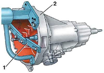
14. Secure the primary shaft against axial movement, for example using a crossbar 1 (2 – clutch housing).
15. Press into crankcase 31 (see Fig. Gearbox type 014) gearbox rear ball bearing 30 primary shaft closed part of the separator towards the crankcase.
16. Install thrust washer 29 and retaining ring 28.
17. Remove cross member and engage one of the gears, securing the primary shaft from turning. Tighten nut 26 at the end of the secondary shaft with a torque of 100 Nm (10 kgf·m) and lock it.
18. Set the fork rods to neutral position.
19. Pull the 3rd and 4th gear shift fork rod back and insert pin 2 into the rod hole (see Fig. Gearbox housing type 014) locking device, having previously lubricated it with a thin layer of consistent grease. Set the fork rod to the neutral position.
20. Select the correct thickness of the adjusting rings for correct installation of the rear bearings of the primary and secondary shafts (see subsection 7.4.1.7)
21. Install spring clip 1 (see Fig. Gear shift housing) on the 2nd gear switch, while the spring leg should rest against the lever on the switch rod.
22. Install into the rear cover of gearbox 16 (see Fig. Gearbox type 014) adjusting washer 25 of the secondary shaft rear bearing.
23. Set all fork rods to neutral position and insert the gear shift lever into the fork rod grooves.
24. Install gasket 21. Then install gearbox cover 16 on gearbox housing studs 31, having first turned it clockwise. Tighten fastening bolts 17, 18 and 19 to a torque of 25 N·m (2.5 kgf·m).