
Table of contents: Removal ↓ Disassembly ↓
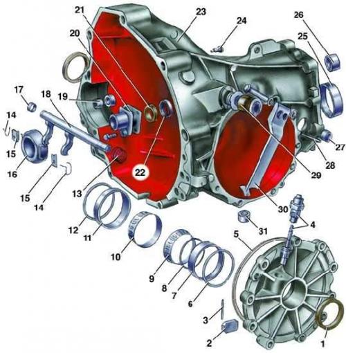
Gearbox type 014
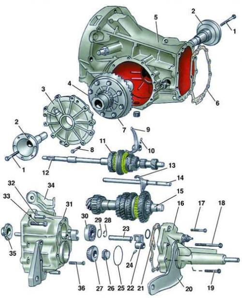
- 1 - bolt;
- 2 - axle shaft flange;
- 3 - differential box cover;
- 4 - differential;
- 5 - clutch housing;
- 6 - gasket;
- 7 - bolt;
- 8 - bolt;
- 9 - 3rd and 4th gear shift fork;
- 10 - pin;
- 11 - 4th gear pinion;
- 12 - primary shaft;
- 13 - 1st and 2nd gear shift fork;
- 14 - 1st and 2nd gear shift fork rod;
- 15 - secondary shaft;
- 16 - back cover;
- 17, 18, 19 - bolts;
- 20 - bracket;
- 21 - gasket;
- 22 - 1st and 2nd gear shift fork rod link;
- 23 - reverse intermediate gear axle;
- 24 - pin;
- 25 - adjusting washer;
- 26 - nut;
- 27 - bearing;
- 28 - retaining ring;
- 29 - washer;
- 30 - bearing;
- 31 - gearbox housing;
- 32 - pin;
- 33 - bolt;
- 34 - bracket;
- 35 - reverse intermediate gear;
- 36 - bolt
Gear shift control mechanism of the 014 type gearbox
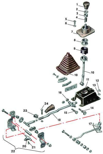
- 1 - handle;
- 2 - retaining ring;
- 3 - washer;
- 4 - spring;
- 5 - bolt;
- 6 - washer;
- 7 - hinge housing;
- 8 - shell;
- 9 - rubber collar;
- 10 - gear shift lever;
- 11 - body;
- 12 - nut;
- 13 - washer;
- 14, 15 - bolts;
- 16 - nut;
- 17 - jet thrust;
- 18 - gear shift rod;
- 19 - case;
- 20 - coupling;
- 21 - screw;
- 22 - wings;
- 23 - terminal;
- 24 - bolt
Gear shift housing
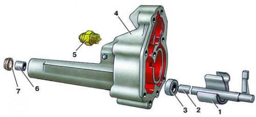
- 1 - spring clip;
- 2 - gear shift;
- 3 - front hub;
- 4 - gearshift housing;
- 5 - Reverse light switch;
- 6 - rear bushing;
- 7 - oil seal
Gearbox housing type 014
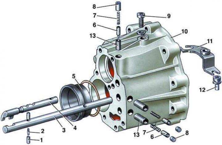
- 1 - plunger;
- 2 - spring pin;
- 3 - 3rd and 4th gear shift fork rod;
- 4 - reverse gear shift fork rod;
- 5 - bearing ring;
- 6 - retainer;
- 7 - spring;
- 8 - cork;
- 9 - bolt;
- 10 - gearbox housing;
- 11 - lever;
- 12 - pin;
- 13 - guide bushing
Primary shaft of gearbox type 014
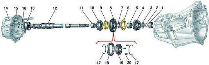
- 1 - needle bearing;
- 2 - retaining ring;
- 3 - adjusting washer;
- 4 - 4th gear pinion;
- 5 - 4th gear needle bearing;
- 6 - 4th gear synchronizer locking ring;
- 7 - retaining ring;
- 8 - synchronizer of 3rd and 4th gears;
- 9 - 3rd gear synchronizer locking ring;
- 10 - 3rd gear pinion;
- 11 - 3rd gear needle bearing;
- 12 - primary shaft;
- 13 - rear bearing of the primary shaft;
- 14 - gearbox housing;
- 15 - retaining ring;
- 16 - adjusting washer;
- 17 - spring;
- 18 - synchronizer sliding clutch;
- 19 - synchronizer hub;
- 20 - synchronizer crackers
Main gear of gearbox type 014
- 1 - oil seal;
- 2 - magnet;
- 3 - pin;
- 4 - speedometer drive;
- 5 - sealing ring;
- 6, 8, 12 - adjusting washers;
- 7, 11 - bearing rings;
- 9, 10 - bearings;
- 13 - return spring;
- 14 - locking bracket;
- 15 - fastening spring;
- 16 - clutch release bearing;
- 17 - bushing;
- 18 - Clutch release fork shaft;
- 19 - starter bushing;
- 20 - Bearing guide sleeve;
- 21 - oil seal;
- 22 - bushing;
- 23 - clutch housing;
- 24 - bolt;
- 25 - bearing ring;
- 26 - needle bearing;
- 27 - filler plug;
- 28 - pin;
- 29 - rubber bushing;
- 30 - clutch lever;
- 31 - drain plug
Removal
1. Place the vehicle on an inspection pit or on a lift.
2. Disconnect the wire from the negative terminal of the battery.
3. Loosen the fastening nut and disconnect the casing with the speedometer drive cable from the speedometer drive housing.
4. Loosen the three upper bolts securing the gearbox to the cylinder block.
5. Loosen the cable tension and disconnect it from the clutch fork lever.
6. Loosen the mounting bolt and disconnect the exhaust pipe with the bracket from the gearbox.
7. Disconnect the front wheel drive shafts from the flanges (see fig. Gearbox type 014) differential output shafts.
8. Disconnect the electrical wires from the gearbox.
9. Unscrew the remaining bolts securing the gearbox to the cylinder block and remove the clutch mud shield.
10. Remove the starter (see subsection 12.1.4.1).
11. Unscrew from the coupling (see Fig. Gear shift control mechanism of the 014 type gearbox) rocker arm screw for fastening the gear shift rod.
12. Remove the torque rod from the ball joint of the rocker arm and disconnect the gear shift rod (see fig. Gear shift housing) from the rocker arm coupling.
13. Place a jack under the gearbox.
14. Loosen the bolts securing the rear powertrain supports on both sides of the gearbox.
15. Carefully move the gearbox back, disengaging the gearbox input shaft from the clutch. Then lower the gearbox and remove it from under the car.
16. Install the gearbox in the reverse order. Before installation, clean and lubricate the splines of the primary shaft with graphite grease, and place the disconnected front wheel drives on the front suspension beam.
Disassembly
1. Clean the gearbox from dirt and wash the outside.
2. Unscrew the oil filler and drain plugs and drain the oil from the gearbox if this has not been done previously.
3. Loosen the mounting bolts (see Fig. Gearbox type 014) and remove the rear cover of the gearbox with the sealing gasket.
4. Remove the secondary shaft rear bearing adjusting washer.
5. Move the 3rd and 4th gear shift fork rod back until the pin is released (see fig. Gearbox housing type 014) locking device and remove the pin.
6. Set the 3rd and 4th gear fork rod to neutral position.
7. Move the 1st and 2nd gear and reverse gear shift rods back, thereby engaging reverse gear and first gear to lock the primary gear (see Fig. Gearbox type 014) and secondary shafts.
8. Unscrew the fastening nut from the secondary shaft.
9. Remove the retaining ring (see Fig. Primary shaft of gearbox type 014) and the adjusting washer from the primary shaft.
10. Disconnect the gearbox housing (see Fig. Gearbox type 014) from the clutch housing.
11. Clamp the gearbox housing by the flange in a vice with soft metal pads.
12. Knock out the spring pin from the 3rd and 4th gear shift fork, placing a support under the rod so as not to damage the hole in the crankcase.
13. Move the rod back and remove the 3rd and 4th gear shift fork.
14. Set the 3rd and 4th gear shift rod to neutral position.
15. Remove the primary shaft from the gearbox housing.
16. Knock out the reverse intermediate gear shaft and remove the reverse intermediate gear.
17. Knock out the spring pin from the 1st and 2nd gear shift rod linkage and remove the linkage from the rod.
18. Press the secondary shaft off the rear tapered roller bearing. Then remove one of the inner bearing races.
19. Unscrew the drive from the differential box cover (see Fig. Main gear of gearbox type 014) speedometer.
20. Loosen the bolt (see fig. Gearbox type 014) fastening the axle flange, fixing the flange through the holes for the mounting bolts using a rod or punch.
21. Loosen the differential cover mounting bolts.
22.Remove the differential cover with the sealing ring using two screwdrivers.
23. Remove the differential assembly from the clutch housing.
24. If it is necessary to replace the front bearing of the secondary shaft, remove the locking pin of the front bearing of the secondary shaft, and then the outer race of the bearing from the clutch housing.
The original publication in its entirety is posted on the website AUDIMANUAL.RU