
Basis
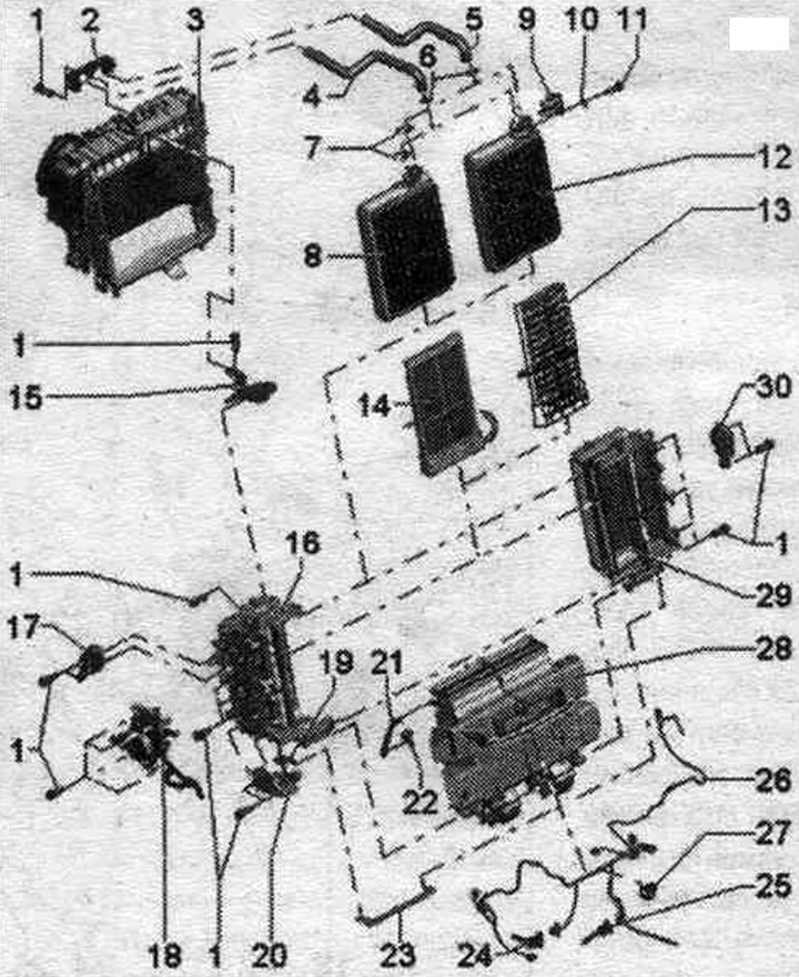
1. Bolt.
2. Coolant pipe holder.
3. Evaporator housing: various designs depending on the production date and vehicle model.
4. Coolant supply pipe for coolant flow from the engine.
5. Coolant supply pipe for the return flow of coolant to the engine.
6. O-ring seal: Replace; before installation, lightly lubricate with coolant.
7. Clamp: These clamps are installed at the factory and hold the coolant lines in place in the factory heat exchanger.
8. Heat exchanger system. heating: this version is set by the manufacturer.
9. Fastening the coolant pipes in the replacement heat exchanger: included in the scope of delivery of the replacement heat exchanger.
10. Washer: included in the scope of delivery of the replacement heat exchanger.
11. Bolt: included in the scope of delivery of the replacement heat exchanger; tightening torque 2.5 Nm.
12. Replaceable heat exchanger system. heating: this version is supplied as a spare part; cover the heat exchanger with foam insulation according to the climate control system, installation and vehicle design.
13. Honeycomb element: is provided for vehicles with a petrol engine and for vehicles with a diesel engine, where the independent heater is controlled as an add. (add. heating element. heater "Z35" is not installed); cover the cellular element with foam insulation according to the climate control installation.
14. Additional heating element. heater "Z35": is intended for vehicles with a diesel engine (also for vehicles with an independent heater (additional equipment) controlled as an add-on) and when certain petrol engines are installed; glue the heating element additionally. heater "Z35" with foam insulation according to the climate control installation version.
15. Bracket.
16. Left heating element housing (with temperature dampers): control of the temperature flaps and, accordingly, the housing of the left heating element is different in cars with the Comfort and Basis climate control systems; with Basis climate control, both temperature flaps (left front panel deflector and left footwell deflector. for the legs) are driven together from the shaft; different designs (with one or two bolt connections at the bottom); lightly lubricate the camshaft guides, shaft bearings, gear elements, and also the journals on the valve levers (e.g. solid lubricating paste -G 000 150-).
17. Defrost flap servomotor "V107".
18. Left mounting plate with footwell flap actuator "V261": with cam disc, intermediate levers and connecting rods; the control of the air flow distribution flaps is different for the Komfort and Basis air conditioning units; with climate control system Basis flaps (front panel deflectors on the left and right and front. deflectors space. for the feet on the left and right) are connected by means of connecting rods in the air distributor housing; rear air vent flaps. for the feet on the left and right are connected by a shaft, all these flaps are driven by an actuator electric motor of the space flap. for legs "V261"; lightly lubricate the camshaft guides, shaft bearings, and camshaft lever journals (e.g. solid lubricating paste -G 000 150-).
19. Dentate segment.
20. Mounting plate with actuator electric motor for temperature flap "V68": control of left and right temperature flaps is different for air conditioning units of the Comfort and Basis versions; with the Basis climate control system, the shaft of the left temperature flaps is driven through a toothed segment from the execution. temperature flap electric motor "V68"); the right temperature valve is also driven by the actuator via a connecting rod operating with this toothed segment. temperature flap electric motor "V68"; lightly lubricate the shaft bearings, toothed segments, and also the journals on the damper levers (e.g. solid lubricating paste -G 000 150-).
21. Defrost flap connecting rod.
22. Intermediate lever to the defroster flap actuator motor "V107".
23. Connecting rod of temperature dampers.
24. Temperature sensor, air vent. for feet "G192": the footwell air temperature sensor "G192" is installed in the left footwell deflector.
25. Temperature sensor, central air vent "G191": the temperature sensor, central air vent "G191" is installed in the air duct to the central air vent of the front panel.
26. Wiring climate control, installation of the Basic version: mark the location of the plugs before pulling them out, (similar plugs for different actuators and temperature sensors can be accidentally mixed up); secure the wiring harness to the mounting points provided on the body using clamps or fasteners so that it does not come into contact with moving parts.
27. Cable clamp.
28. Air distributor housing, climate control, Basis version installation: do not disassemble into parts; various versions for cars with air conditioning in the Comfort and Basis versions; lightly lubricate the camshaft guides, shaft bearings, gear elements, and also the journals on the valve levers (e.g. solid lubricating paste -G 000 150-).
29. Right heating element housing (with temperature dampers): control of the temperature flaps and, accordingly, the right heating element housing is different on vehicles with Komfort and Basis climate control. With Basis climate control, both temperature flaps (right front panel deflector and right footwell deflector. for the legs) are driven together from the shaft;different designs (with one or two bolt connections at the bottom; lightly lubricate the camshaft guides, shaft bearings, gear elements, and also the journals on the valve levers (e.g. solid lubricating paste -G 000 150-).
30. Executive drive of the central deflector "V102".
Komfort
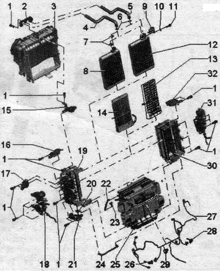
1. Bolt.
2. Coolant pipe holder.
3. Evaporator housing: various designs depending on the production date and vehicle model.
4. Coolant supply pipe for coolant flow from the engine.
5. Coolant supply pipe for the return flow of coolant to the engine.
6. O-ring seal: Replace; before installation, lightly lubricate with coolant.
7. Clamp: These clamps are installed at the factory and hold the coolant lines in place in the factory heat exchanger.
8. Heat exchanger system. heating: this version is set by the manufacturer.
9. Fastening the coolant pipes in the replacement heat exchanger: included in the scope of delivery of the replacement heat exchanger.
10. Washer: included in the scope of delivery of the replacement heat exchanger.
11. Bolt: included in the scope of delivery of the replacement heat exchanger; tightening torque 2.5 Nm.
12. Replaceable heat exchanger system. heating; this version is supplied as a spare part; cover the heat exchanger with foam insulation according to the climate control system, installation and vehicle design.
13. Honeycomb element: intended for vehicles with a petrol engine without an additional heating element. air heater "Z35" and for vehicles with a diesel engine, where the independent heater is controlled as an additional one ("Z35" is not installed); cover the cellular element with foam insulation according to the climate control installation.
14. Additional heating element. heater "Z35": is intended for vehicles with a diesel engine (also for vehicles with an independent heater (additional equipment) controlled as an add-on) and when certain petrol engines are installed; glue the heating element additionally. heater "Z35" with foam insulation according to the climate control installation version.
15. Bracket.
16. Mounting plate with actuator electric motor of left temperature flap "V158".
17. Defrost flap servomotor "V107".
18. Left mounting plate with actuator electric motor of the air vent valve. for the left footwell "V108" and with the actuator electric motor of the left central deflector "V110": with disc cams, intermediate lever and connecting rods; lightly lubricate the camshaft guides, shaft bearings, and camshaft lever journals (e.g. solid lubricating paste -G 000 150-).
19. Left heating element housing (with temperature dampers): control of the temperature flaps and, accordingly, the housing of the left heating element is different in cars with the Comfort and Basis climate control systems; with Comfort climate control system, temperature dampers (front left and rear) are driven by various electric motors;different designs (with one or two bolt connections at the bottom; lightly lubricate the camshaft guides, shaft bearings, gear elements, and also the journals on the valve levers (e.g. solid lubricating paste -G 000 150-).
20. Dentate segment.
21. Mounting plate with rear actuator electric motor. temperature flap "V137": control of the left and right temperature flaps is different for the Komfort and Basis air conditioning units; with air conditioning system Comfort, left rear shaft. the temperature damper is driven through a toothed segment from the actuator. electric motor rear. temperature valve "V137"; the right rear temperature valve is also driven by the actuator via a connecting rod operating with this toothed segment. electric motor rear. temperature valve "V137"; lightly lubricate the shaft bearings, toothed segments, and also the journals on the damper levers (e.g. solid lubricating paste -G 000150-).
22. Defrost flap connecting rod.
23. Intermediate lever to the defroster flap actuator motor "V107".
24. Connecting rod of rear temperature flaps.
25. Air distributor housing, climate control, Comfort version installation: do not disassemble into parts; various versions for cars with air conditioning in the Comfort and Basis versions; lightly lubricate the camshaft guides, shaft bearings, gear elements, and also the journals on the valve levers (e.g. solid lubricating paste -G 000 150-).
26. Temperature sensor, air outlet in the left footwell "G261": The temperature sensor, supplied air in the left footwell "G261" is installed in the left footwell deflector.
27. Climate control wiring harness, Comfort version settings: mark the location of the plugs before removing them (similar plugs for different actuators and temperature sensors can be accidentally mixed up): secure the wiring harness to the mounting points provided on the body using clamps or fasteners so that it does not come into contact with moving parts.
28. Temperature sensor, air outlet in the right footwell "G262": the temperature sensor, supplied air in the right footwell "G262" is installed in the footwell deflector. for the legs on the right.
29. Cable clamp.
30. Right heating element housing (with temperature dampers): control of the temperature flaps and, accordingly, the housing of the right heating element is different in cars with the Comfort and Basis climate control systems; with Comfort climate control system, temperature dampers (front right and rear right) are driven by various actuator electric motors; different designs (with one or two bolt connections at the bottom); lightly lubricate the camshaft guides, shaft bearings, gear elements, and also the journals on the valve levers (e.g. solid lubricating paste -G 000 150-).
31. Right mounting plate with actuator electric motor of the air vent valve. for the right feet "V109" and with the actuator electric motor of the right central deflector "V111"; with disc cams, intermediate lever and connecting rods; lightly lubricate the camshaft guides, shaft bearings, and camshaft lever journals (e.g. solid lubricating paste -G 000 150-).
32. Mounting plate with actuator electric motor of right temperature flap "V159".
Disassembling and assembling the evaporator housing
Removing the air conditioner. Remove the evaporator housing from the air conditioner.
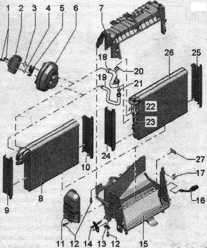
1. Bolt.
2. Expansion valve: removed when removing the air conditioner.
3/4. O-ring: replace.
5. Mounting plate.
6. Rubber tip: For insulating the hole for refrigerant pipes through the rear wall of the water drain box; the built-in support ring is removed when removing the air conditioner, ensure that it is in the correct position.
7. Evaporator body, upper part.
8. Evaporator: this version is installed by the manufacturer.
9. Evaporator cover: make sure it is properly secured to the evaporator.
10. Evaporator cover: ensure that it is properly secured to the evaporator.
11. Refrigerant hose cover: ensure it is properly secured to the evaporator body.
12. Bolt.
13. Bracket.
14. Climate control holder, installation on the central tunnel: with the help of this holder, deviations in the position of the climate control installation relative to the central tunnel are compensated.
15. Evaporator body, lower part.
16. Temperature sensor, refrigerant at the outlet of the evaporator "G263".
17. Bracket.
18. Refrigerant tube to the replacement evaporator: included in the scope of delivery of the replacement evaporator; available only for evaporator with block width approx. 40 mm.
19. Refrigerant tube to the replacement evaporator: included in the scope of delivery of the replacement evaporator; available only for evaporator with block width approx. 40 mm.
20. O-ring connection seal on the replacement evaporator: included in the scope of delivery of the replacement evaporator.
21. O-ring connection seal on the replacement evaporator: included in the scope of delivery of the replacement evaporator.
22. Fastening the refrigerant tubes in the connection on the replacement evaporator: included in the scope of delivery of the replacement evaporator.
23. Bolt: included in the scope of delivery of the replacement evaporator; tightening torque 5 Nm.
24. Replacement evaporator cap: included with the replacement evaporator; ensure correct fastening on the evaporator; depending on the design, the cover may need to be modified in the area where the refrigerant tubes connect to the evaporator before installation.
25. Replacement evaporator cap: included with the replacement evaporator; ensure that it is properly secured to the evaporator.
26. Replacement evaporator: this version is supplied as a spare part.
27. Dividing wall: included in the scope of delivery of the replacement evaporator; this separator is installed in the lower part of the evaporator body after installing the replacement evaporator.