
Table of contents: Instructions for general repair of a… ↓ Overview of the components of a… ↓
Instructions for general repair of a car with an independent heater
Before starting electric welding work on the vehicle, disconnect the (-) and positive terminals from battery "A". If the coolant has been drained, then after filling the system. cooling, remove air from the independent heater. If fuel elements have been removed or replaced. system, make sure that all additional power components are working. the heater fuel gauges are installed correctly. Then turn on the independent heater and let it run for at least 10 minutes at full load to ensure complete removal of air from the fuel. highway and check the operation of the independent heater. After completing repair work on the fuel line to the independent heater, it is necessary to check: the absence of air in the fuel. the main line going to the independent heater; fuel location. highways flush with the bottom of the car and the presence of protection from mechanical damage. damage; that the fuel line to the independent heater is protected from excessive heating; lack of fuel contact. highways with heating units. When carrying out repair work in the area of the fuel supply module, take into account the correct routing of the fuel take-off line for the independent heater in the fuel. tank. If the fuel line is incorrectly routed, the "V54" metering pump can only deliver fuel when the tank is fully filled with fuel. tank (if the tank is not full, fuel will not be supplied and the independent heater will shut down due to a malfunction). After removing and installing fuel components. system, it is necessary to turn on the independent heater and operate it under full load for at least 10 minutes to completely remove air from the fuel. highways. If in the fuel. if the tank is too low on fuel (the fuel gauge needle in the used instrument cluster "J285" is in the red zone), then the used auxiliary heater "J364" does not turn on the independent heater (prohibition of inclusion due to lack of fuel via the data bus). Before switching on or while the auxiliary heater is running, the auxiliary heater "J364" queries the data bus diagnostic interface "J533"/6/y of the battery monitoring system "J367" via the data bus. If the data bus diagnostic interface "J533" reports an energy saving message due to an insufficiently charged battery or too low voltage in the on-board network, the auxiliary heater "J364" switches off the auxiliary heater.
Overview of the components of a stand-alone heater in a car
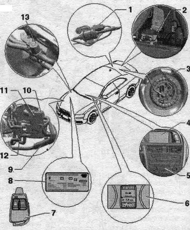
1. Dosing pump "V54": check the fuel supply volume; depending on the vehicle version, a silencer may be built into the fuel line leading to the independent heater in the area of the "V54" metering pump to reduce noise.
2. Radio receiver for independent heater "R64": various versions of the radio signal receiver for independent heater "R64" are available.
3. Fuel supply module with a fuel withdrawal pipe for an independent heater: various fuel supply modules, depending on the type of vehicle (petrol or diesel, front or all-wheel drive).
4. Multimedia Interface (MMI): Via the MMI, various control functions of the auxiliary heater and auxiliary ventilation are entered and displayed on the corresponding display.; independent heater control, MMI (in the Sag menu), multimedia interface and the corresponding display indications are described in the corresponding operating manual; if in fuel. the tank is too low on fuel (the fuel gauge needle is in the red zone), i can't turn on the independent heater (the checkbox in the MMI for the function "Immediate activation of the auxiliary heater" and the auxiliary heater icon on the clock do not turn on or go out immediately).
5. Used and indicators, used Climatronic "J255": receives control signals via the data bus; when the independent heater is turned on using the Timer function or the remote control, it decides in which mode to turn on the independent heater (autonomous ventilation or autonomous heater); to turn on the independent heater using the Timer function or remote control (key fob), you must select a temperature higher than Lo on the control panel and display of the used Climatronic "J255"; to ensure that the windows are cleared of ice as quickly as possible, it is recommended to set the used Climatronic "J255" to the highest possible temperature before turning off the ignition; used and indicators, used Climatronic "J255" uses the last set temperature in the operation of the independent heater and regulates the temperature in the cabin in accordance with the set temperature.
6. Instrument cluster display: installed in the instrument panel; depending on the version, the additional equipment of the independent heater should be configured using the Adaptation function in the used version in the instrument cluster "J285"; if in fuel. the tank is too low on fuel (the fuel gauge needle on the instrument panel is in the red zone), it is not possible to turn on the independent heater (the check mark in the MMI, in the function "Immediate activation of the independent heater" and the independent heater icon on the clock do not turn on or go out immediately); depending on the operating condition of the independent heater (autonomous heating/ventilation mode.) or when selecting the Timer 1 function from the symbols for independent heating or independent ventilation. will be constantly controlled or both symbols will flash; if a remote radio control of the independent heater is installed (additional equipment), then you can control the used additional heater "J364" from it; then the remote control transmits the message "Autonomous heater/autonomous ventilation on or off" via the data bus to the control and display panel of the used Climatronic "J255"; the control and display panel then decides whether the independent heating mode must be turned on to achieve the set temperature, or whether the independent ventilation mode is sufficient.
7. Remote control of the independent heater: to switch on and off the Independent heater or Independent ventilation function of the independent heater; when you press the keys, the built-in control lamp lights up or flashes; replace the batteries; in order for the remote control to recognize the key press and send a radio signal, you must hold the key down for at least 3 seconds; if you are replacing a used auxiliary heater "J364", you should check the operation of at least one remote control and, if necessary, reconfigure all remote controls; after removing the power sources, it is necessary to determine the type of remote (radio) control using the part number on the sticker.
8. Duplicate nameplate of the independent heater: in addition to technical characteristics, it indicates the type of independent heater; glued to the inside of the hood.
9. Exhaust noise muffler for independent heater.
10. Intake air noise muffler.
11. Autonomous heater: check the el. components of an independent heater: the following el. components are installed in the independent heater. components: used additional heater "J364", temperature sensor. "G18", flame sensor "G64", temperature sensor. 2 additional and autonomous heaters "G587", heater glow plug "Q9", combustion chamber air supply fan "V6", heating element of the system. fuel preheater "Z66".
12. Circulation pump "V55": the circulation pump "V55" is controlled by the used auxiliary heater "J364": depending on the vehicle configuration, the used auxiliary heater "J364" can turn on the circulation pump "V55" even when the auxiliary heater is switched off, upon a request received via the data bus (a request, for example, from the used engine or from the control panel. controls, and display used Climatronic "J255").
13. Heater coolant supply shut-off valve "N279": in the autonomous heating mode, the used additional heater "J364" is controlled; in vehicles with a 4- or 6-cylinder petrol engine, the heater coolant supply shut-off valve "N279" can receive control signals even when the independent heater is turned off (for example, with certain adjustments using the control panel. control and display of the Climatronic control unit "J255" for blocking the coolant supply to the climate control heat exchanger); different designs (on Audi A5 Coupe, Audi A4 and Audi Q5), pay attention to the correct match; check the wired connection
(The text is based on materials from the website «audimanual.ru»)