
Before making a decision on repair, it is necessary to diagnose the state of the coupling of units. As a rule, diagnostics are carried out according to indirect signs such as; increased noise, vibration, oil consumption, crankcase gas breakthrough, etc. For a more high-quality diagnosis, the unit must be disassembled, the parts washed, inspected and subjected to micrometric measurements. Based on the results of the inspection and micrometric measurements, a decision is made to continue operation without repair or to carry out repairs. In this case, the following considerations should be followed: if the actual dimensions of the parts are within the tolerance fields permitted by this Manual, then continued operation of the unit without repair is possible; if the dimensions are outside the permissible tolerance fields, then repair is necessary. The extensions of the tolerance fields given in this Manual should be understood as the possibility of using the residual resource of the unit without restoring the couplings. In the case of repair of the unit, when restoring the couplings, the extension of the tolerance fields beyond the nominal ones is not allowed.
The repair technology is usually divided into four main stages of work:
- 1. Disassembly and washing.
- 2 Control sorting.
- 3. The actual repair is the restoration of the micro and macro geometry of the surfaces of parts and their physical and mechanical properties.
- 4. Assembly with preliminary inspection of parts arriving for assembly.
Disassembly and washing operations are carried out in several stages - external washing of the unit, partial disassembly, unit washing, disassembly into parts, washing and cleaning of parts. All parts must be thoroughly cleaned of dirt and carbon deposits, degreased, washed and dried before inspection and sorting.
Clean oil channels and holes in parts, flush under pressure and blow out with compressed air.
Parts and j of aluminum and zinc alloys must not be washed in alkaline solutions used for washing steel and cast iron parts, since aluminum and zinc dissolve in alkalis.
During the inspection of parts, breaks, cracks, dents, cavities and other damages are detected by visual inspection. The presence of cracks in critical parts is checked using a flaw detector. The dimensions of parts must be checked in places of greatest wear. Gear teeth wear unevenly, so when inspecting them, at least three teeth located at an angle of approximately 120° must be measured. Due to the need to guarantee the operation of gear transmissions during the entire inter-repair run, chipping on teeth and flaking of the working surface of teeth due to fatigue are not allowed.
Assembly units such as: connecting rod with connecting rod cap, cylinder block with main bearing caps, gearbox gears and main gear cannot be disassembled. Other assembly units can be disassembled, but if a decision is made to continue operating the mating elements without repair, then it is inappropriate to disassemble them.
In all cases of repair of parts by welding and surfacing, the weld seam must have no slag inclusions, unchecked areas, undercuts and other defects. Clean the seam after welding. Remove metal burrs so that they do not interfere with the installation of the mating parts.
Holes with worn or damaged threads are restored by cutting a thread of an increased repair size, welding the hole with subsequent cutting of a nominal size thread, installing inserts and spiral threaded inserts. The use of threaded inserts is preferable for reasons of restoration quality and labor costs.
The insert is a springy spiral made of diamond-shaped wire. At one end of the spiral, a technological leash is bent, by means of which the insert is screwed into a pre-prepared hole.
The technological process of repairing a threaded hole using a spiral insert includes the following operations: drilling the defective hole to a certain size, cutting a thread in it corresponding to the size of the spiral insert, screwing in the spiral insert and breaking off the technological leash along the notch.
The table shows the sizes of holes and threads for spiral inserts used in the repair of automotive parts.
Table of drill and tap sizes for spiral inserts
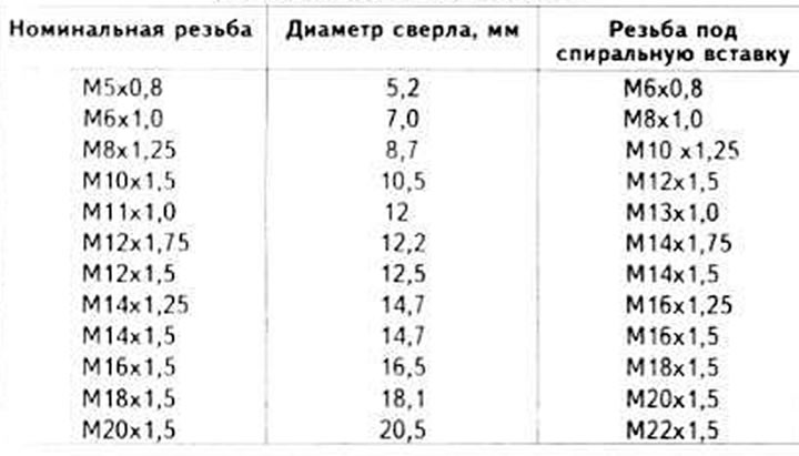
For repairing threaded holes with spiral inserts, a special kit is produced, which includes: inserts, drills, special taps, keys for screwing in inserts, punches for cutting off the technological leash.
Parts supplied for assembly must be clean and dry.
Threaded connections must be undamaged. Disposable self-locking threaded fasteners must be replaced with new ones. If it is impossible to use new self-locking parts, when installing old ones, they must be additionally locked from unscrewing.
When assembling, install new gaskets and seals. Lubricate the rubbing surfaces of the parts with clean oil during assembly. When installing rubber seals, lubricate the working surface of the cuff to avoid damage during installation. When installing seals with a metal body, lubricate the seat under the seal with a thin layer of sealant.
Assembly of units and assemblies must be carried out in accordance with this Manual.
Using a measuring instrument, check the dimensions of the parts that form the fit before assembly.
When assembling parts that have a flexible fit in the mating, their free relative movement must be ensured, without jamming. Bushings, rings of ball and roller bearings must be installed using mandrels. When pressing in bearings, the force must not be transmitted through the balls or rollers. Pressing tools must rest against the ring being pressed in. The pressing force must coincide with the bearing axis to avoid ring skewing.
If, according to the assembly conditions, the installation of critical parts is carried out by hammer blows, it is necessary to use mandrels and hammers made of non-ferrous metals, plastic, rubber, as well as devices for pressing in parts.
The keys must be tightly seated in the shaft keyways using a hammer or a non-ferrous metal mandrel. No play in the keys in the shaft keyways is allowed.
The studs must be screwed into the threaded holes tightly without any play. The parts must be put on the studs freely. Bending the studs when installing parts on them is not allowed, the fastening of the unit or part with several nuts or bolts must be done evenly around the perimeter - first preliminary, and then finally. All nuts or bolts of one connection must be tightened with the same torque.
In all cases provided for in the Manual, it is necessary to use keys that allow limiting the torque.
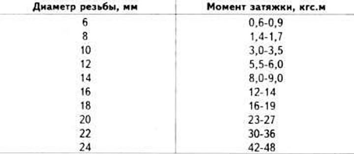
Tightening torques for threaded connections, unless specifically specified in the technical specifications, are determined depending on the thread diameter in accordance with the table.
Table of tightening torques for threaded connections
The bolt should protrude from the nut (except in specially specified cases) on two or three threads.
The cotter pins should not protrude from the nut slots. The ends of the cotter pins should be spread and bent - one on the bolt, and the other on the nut.
When assembling, blow out the fuel and brake lines with compressed air.
[This article was previously published on the resource: AudiManual.ru]