
Table of contents: Removal and installation a… ↓ Removal and installation the air… ↓ Removal and installation the air… ↓
Removal and installation a compressor with a mechanical drive
(a/m with a 4-cylinder engine)
Turn off the ignition. Drain the refrigerant from the circuit. Remove the front sound insulation. Remove the air conditioning circuit pipes from the compressor. The procedure varies depending on the engine and power steering pump. Depending on the pump model, you may first need to remove the compressor from its mount, followed by the refrigerant hoses. The vane pump is installed only on vehicles without electric power steering. Removing the compressor from the holder.
Installation
Installation in reverse order. The removed compressor contains an unknown amount of compressor oil, so follow the instructions for replacing the compressor. Before installing the poly V-belt, rotate the compressor pulley 10 revolutions in the direction of rotation (to avoid damage to the compressor when first turned on). Installing the compressor on the holder. Install the air conditioning circuit tubes onto the compressor. Before installation, lightly moisten the seal. rings with compression oil. When the compressor is cranked, compressor oil, which may be present in the compression chamber, helps prevent damage to the compressor. Evacuate and fill the refrigerant circuit. Install all remaining elements. Turn on the ignition. Query memory faulty. control and display module, used Climatronic "J255" and remove possible displayed faults. Put the air conditioning system into operation after charging the refrigerant circuit.
Removal and installation the air conditioning compressor
(cars with a 6-cylinder TDI engine)
Turn off the ignition. Drain the refrigerant from the circuit. Remove the "arrow" engine cover.
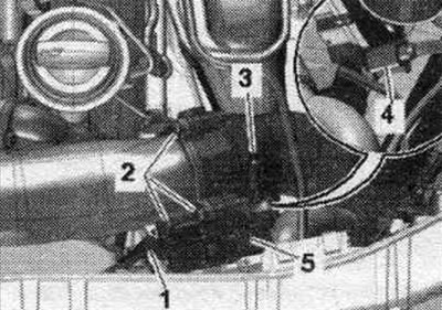
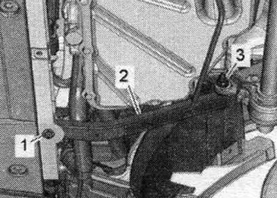
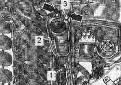
Remove the oil dipstick "1" (if available). Remove the air hose by opening the clamp "3". Disconnect the electrical. plug "4". Unscrew bolts "2" and remove the used throttle valve "J338".
Remove coolant hose "3" from the expansion tank. Unscrew the bolts "arrows" and put the expansion tank aside. tank with hoses "1" and "2" connected to the side.
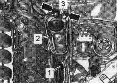
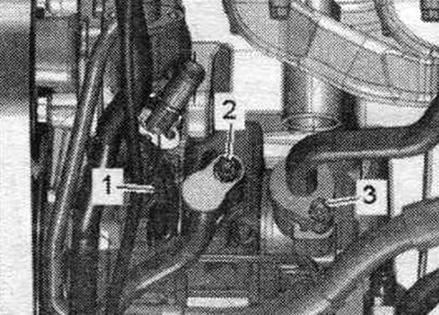
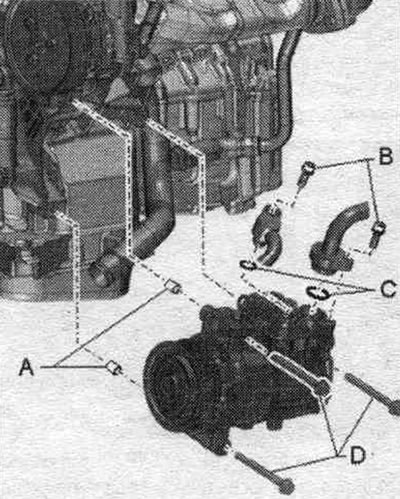
Disconnect plug "1" from the air conditioning compressor regulating valve "N280". Remove bolts "2" and "3" and remove the refrigerant hoses from the air conditioning compressor.
Remove the front sound insulation. Depending on the vehicle design, the front wheel must be removed. noise protection screen may require removal of the bumper cover (on the Audi A4 allroad).
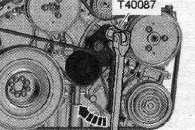
To loosen the poly V-belt, use a Torx T60 "T40087" socket to move the tensioner in the direction of the arrow. Remove the poly V-belt from the air conditioning compressor pulley and relieve the tensioner.
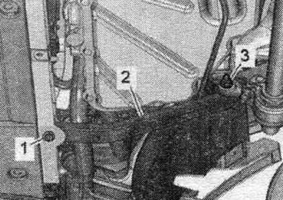
Unscrew the left bolt "1" and nut "3" and remove the longitudinal rod "2". Disconnect (if available) power steering vane pump from bracket (sometimes it is not necessary on a car with a flexible pressure line to the pump), tilt it to the side and attach it, for example, with wire to the engine.
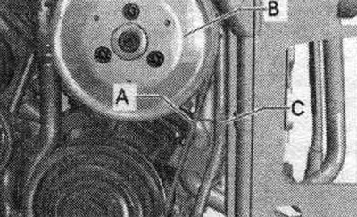
The pressure line to the power steering pump "C" is secured to the compressor with a bracket and a mounting bolt. When removing the compressor, do not bend the pressure line to the power steering pump "C" more than necessary (maximum 5 mm). If removing the compressor requires bending the pressure line of vane pump "C" of unit "A" by more than a maximum of 5 mm, disconnect the vane pump from the engine, pull it forward, set it aside, and secure it to the engine, for example, with wire. In this case, do not bend or stretch the line to the pump. The pressure line to the vane pump is available in different designs (rigid or flexible). The pressure line and vane pump are installed only on vehicles without mechanical power steering.
Unscrew the "arrow" screws and remove the compressor.
Installation
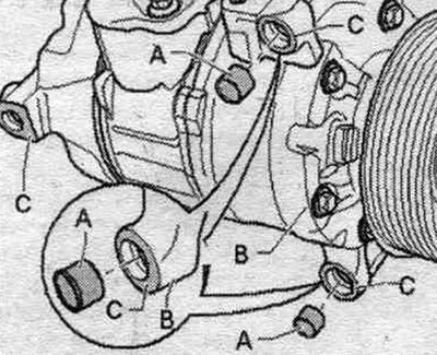
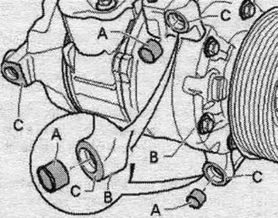
Installation is in reverse order, taking into account the following. The removed compressor contains an unknown amount of compressor oil, so it is necessary to follow the compressor replacement instructions. If necessary, remove the guide bushings "A" from the compressor. Thoroughly clean the compressor mating surfaces and the air conditioning system. Install guide bushings "A" into the compressor.
Pay attention to the fit of the centering bushings and the cleanliness of the mating surfaces. Incorrectly installed centering bushings, dirty or damaged mating surfaces can cause misalignment between the air conditioner compressor and the engine. Misalignment during operation leads to damage to the poly V-belt, drive shaft or compressor. Centering bushings "A" are available in a variety of designs (different lengths), select the required version from the Electronic Parts Catalog. Ensure that the bushings "A" are correctly seated and that the mating surfaces are clean. Incorrectly installed bushings, dirty or damaged mounting surfaces "C" of the bracket or compressor can cause misalignment of the compressor and engine. Misalignment during operation can lead to damage to the poly V-belt or compressor.
Tighten the arrow bolts. Tightening torque: 25 Nm. Install the refrigerant hoses on the compressor; tightening torque of bolts "B"), dimensions of O-rings "C" and other indications. Before installing the poly V-belt, rotate the compressor pulley 10 revolutions in the direction of rotation (to avoid damage to the compressor when first turned on). To install the poly V-belt, move the tensioner back using the Torx T 60 socket "T40087" in the "direction of the arrow". Install the throttle valve control unit "J338". Install the longitudinal strut. Secure all hose connections with clamps of the appropriate series. In order to securely fasten the air hoses to the connecting fittings, it is necessary to lubricate the augers of used clamps with a rust solvent. After tightening the compressor bolts and installing the refrigerant hose, check the refrigerant line routing; they must be inserted into the holders provided for this purpose (if any, depending on the engine). Make sure that the refrigerant lines and the corresponding brackets are installed at a sufficient distance from other parts, and pay attention to the sufficient distance between the belt, bracket and belt pulley.
Evacuate and fill the refrigerant circuit. Install all remaining elements. Query memory faulty. control and display module, used Clmatronic "J255" and remove possible displayed faults. Put the air conditioning system into operation after charging the refrigerant circuit.
Removal and installation the air conditioning compressor
(a/m with a 6-cylinder gasoline engine)
Turn off the ignition. Drain the refrigerant from the circuit. Remove coolant hose "3" from the expansion tank. Unscrew the bolts "arrows" and put the expansion tank aside. tank with hoses "1" and "2" connected to the side.
Remove the left air filter assembly. Remove the front sound insulation. Unscrew bolts "1" and nuts "3" and remove the left longitudinal rod "2". Remove the front left wheel and the front left fender liner.
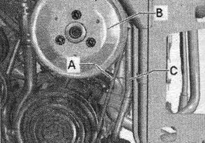
Mark the direction of rotation of the poly V-belt "A". Remove the poly V-belt "A". Crimp (if available) supply line to the power steering impeller pump "B" with clamps for hoses up to 25 mm "3094". Remove (if necessary) pressure line "C" to the power steering impeller pump "B".
In this case, pay attention not to bend, flex or stretch the pressure line to the pump. When removing the compressor, do not disconnect the power steering impeller pump "B" from the bracket. The pressure line and vane pump are installed only on vehicles without mechanical power steering. Discharge line of the vane pump "C" (top drawing) is attached above the bracket with the "C" mounting bolt (bottom drawing) to the compressor.
Remove the air conditioning circuit pipes from the compressor. Remove the refrigerant hoses from above.
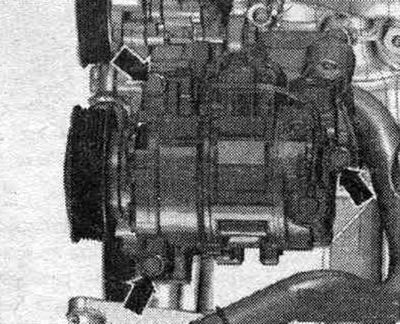
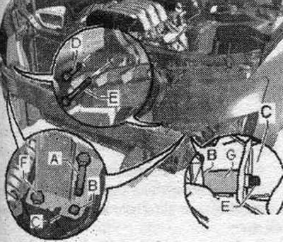
Disconnect the electrical. plug "A". Unscrew bolt "B" (and bolt "C") (tightening torque 25 Nm). Bolt "C" (tightening torque 25 Nm) on a car with a vane pump, it was already unscrewed when removing the pressure line of the vane pump. The pressure line and vane pump are installed only on vehicles without mechanical power steering. This is the drawing shown is a compressor in a car with a "V51" coolant circulation pump (not installed in all vehicles). In other vehicle configurations, it may be necessary to drain the coolant and remove "V51" in order to remove the compressor. Depending on the compressor design and the car model (different coolant fans, water cooler and hose connection "V51") it may be necessary to additionally bring the lock console into service. position (so that the compressor can be turned downwards).
Instructions for bringing the lock console into service position
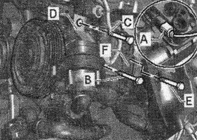
If you first unscrew the bolts "A", and after unscrewing the bolt "A" mark the position of the lock console "B" (through the holes on the left and right), for example, with a waterproof marker on the longitudinal traction "C", then the console can subsequently be installed in exactly the same place. If you unscrew both "D" bolts and install longer "E" bolts in their place (for example, M10 x 100), after unscrewing the "F" bolts, you can move the lock console forward approximately 60 mm. Using the "G" bushings (or a suitable wooden stick 60 mm long) you can fix the console of the "C" lock, preventing it from slipping.
Remove bracket "D". Unscrew bolt "E" (tightening torque: 25 Nm). Remove the "F" compressor from the bracket, move it forward and then down.
Installation
Installation in reverse order. Before securing the compressor, check the position of both centering bushings "A" in the bracket or in the compressor "B". Centering bushings "A" come in a variety of designs (different lengths), select the required version from the Electronic Parts Catalog. Ensure that the bushings "A" are correctly seated and that the mating surfaces are clean. Incorrectly installed bushings, dirty or damaged mounting surfaces "C" of the bracket or compressor can cause misalignment of the compressor and engine. Misalignment during operation can lead to damage to the poly V-belt or compressor. Before installing the poly V-belt, rotate the compressor pulley 10 revolutions in the direction of rotation (to avoid damage to the compressor when first turned on). Install the pressure line to the power steering impeller pump. Install the poly V-belt "A".
Install the air conditioning circuit tubes onto the compressor. Before installation, lightly moisten the seal. rings with compression oil. When the compressor is cranked, compressor oil, which may be present in the compression chamber, helps prevent damage to the compressor. After tightening the compressor bolts and installing the refrigerant hose, check the refrigerant line routing; they must be inserted into the holders provided for this purpose (if any, depending on the engine). Make sure that the refrigerant lines and the corresponding brackets are installed at a sufficient distance from other parts, and pay attention to the sufficient distance between the belt, bracket and belt pulley. Evacuate and fill the refrigerant circuit. Install all remaining elements. Query memory faulty. control and display module, used Climatronic "J255" and remove possible displayed faults. Put the air conditioning system into operation after charging the refrigerant circuit.