
Air duct in the air intake box and in the air conditioner
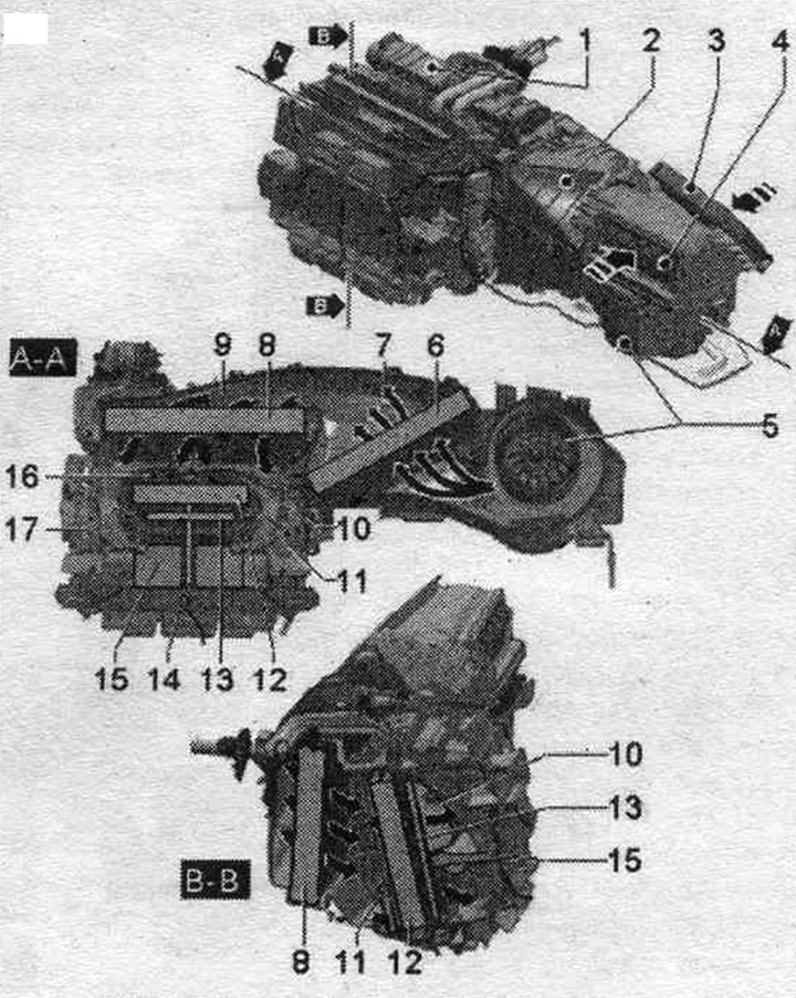
1. Climate control system: various designs, depending on the climate control system design (Comfort and Basis).
2. Air intake box.
3. Outdoor air intake: air comes from the water discharge box.
4. Air intake from the cabin (in air recirculation mode): When the recirculation flap is open, air is sucked in from the space under the glove compartment. for legs per. passage.; the figure shows the recirculation damper in the closed position.
5. Supply fan "V2".
6. Cabin filter: the cabin filter is available in different versions: with or without an activated carbon filter insert.
7. Lower part of the air intake box (with additional elements); in the figure, the air intake box is indicated by line A - A (in section).
8. Evaporator.
9. The bottom of the air conditioner (with additional elements); in the figure, the air conditioner is indicated by line A - A (in section).
10. Temperature damper front. deflectors on the right: the figure shows the temperature flap in the heating position; with the Comfort air conditioning system, the temperature flaps on the left and right are driven by separate actuator electric motors, both temperature flaps of the rear deflectors are connected to each other by means of a connecting rod, they are driven by an additional. electric motor; with the Basis climate control system, the temperature flaps in the front and rear footwell are connected to each other by a shaft, both shafts of the temperature flaps on the right and left are connected to each other by a connecting rod, they are driven by an additional. electric motor.
11. Temperature flap for rear right vents: The figure shows the temperature flap in the cooling position.
12. Heat exchanger system. heating: covered with various seals made of foam material depending on the design and equipment of the climate control system, installation (Comfort and Basis).
13. Additional heating element. heater "Z35"/honeycomb element: additional heating element. the "Z35" heater is installed on vehicles with diesel engines and on vehicles with certain gasoline engines; on vehicles with petrol engine (without additional heating element. heater "Z35") to fill the free space. a cellular element is installed (this ensures the same air flows in the air conditioner with additional heating element. heater "Z35" and without it); if a diesel car is equipped with an independent heater as an additional one. heater (additional equipment), then an additional heating element is not used here. heater "Z35", and the cellular element (the question of use remains open); covered with various seals made of foam material depending on the design and equipment of the climate control system, installation (Comfort and Basis).
14. Dividing wall: installed only on vehicles with the Comfort air conditioning system (there is no such option on Basis, here you can only set one tempo for all deflectors); in the Comfort version, it divides the air duct to the deflectors on the left and right and is necessary to ensure different temperatures of the supplied air (depending on the position of the corresponding temperature valve), the temperature of the outgoing air depends on the position of the corresponding temperature damper.
15. Dividing wall: installed only on vehicles with the Comfort air conditioning system (there is no such option on Basis, here you can only set one tempo for all deflectors); on the Comfort version, it divides the air duct to the deflectors at the front and rear and is necessary to ensure different air temperatures at the front and rear (depending on the position of the corresponding temperature valve).
16. Temperature flap for rear vents on the left: the figure shows the temperature flap in the heating position.
17. Temperature damper front. deflectors on the left: the figure shows the temperature flap in the cooling position.
(This publication is borrowed from the resource «AUDIMANUAL.RU»)