
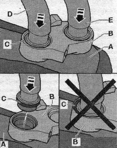
Note: Factory heat exchanger due to limited space with front panel installed (and installed air conditioning) due to the presence of brackets "B" and "C", it cannot be reinstalled or can be installed, but with insufficient reliability. If it is necessary to reinstall the factory heat exchanger (original part) it is necessary to remove the front panel and the air duct to the deflector for defrosting. Install the O-rings, lightly lubricated with coolant (as described for installation of heat exchanger spare parts), on the coolant pipes "D" and "E" and press the coolant pipes "D" and "E" (with O-ring seals) from above, connect to heat exchanger connections "A." Hold coolant pipes "D" and "E" in the heat exchanger and install clamps "B" and "C." Further assembly is similar to the description for the replacement heat exchanger.
Prepare for heat exchanger removal. Relieve pressure in the coolant circuit by opening the expansion tank cap. system tank. cooling. Mark the location of the coolant hoses "A" (pre-supply line from the cylinder head) и "B" (return line to the water pump). The heat exchanger is positioned according to a specific direction of coolant flow, so the coolant hoses must be connected correctly on all sides. System hoses. cooling pipes "A" and "B" should be clamped using hose clamps. Cover the areas under the coolant hose connections "A" and "B" in the water drain box with, for example, absorbent paper. Remove coolant hoses "A" and "B" from the air conditioner heat exchanger fittings.
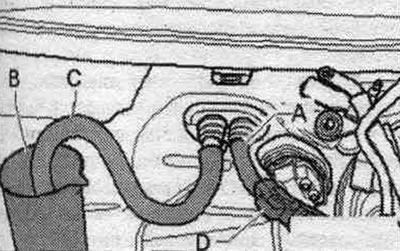
Attach a piece of hose ("A" and "C") to both connections to the heat exchanger. Place container "B" under the other end of hose "C". Using air gun "D", carefully blow coolant from the heat exchanger through hose "A" (into container "B").
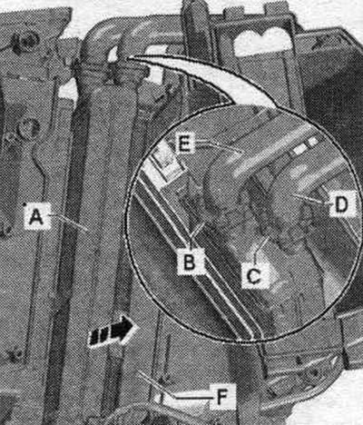
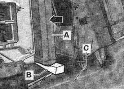
Remove clamps "B" and "C" from heat exchanger connections "A". Disconnect both coolant pipes "D" and "E" from heat exchanger connections "A". Remove heat exchanger "A" in the direction of the arrow. In the upper figure a heat exchanger with factory connections is presented. If the heat exchanger has already been replaced once, both coolant pipes in the replacement heat exchanger being installed are held in place by fastener "A." On this heat exchanger, loosen bolt "B." Then, screw in the longer bolt "C" (M5 thread), as shown in the figure, until it stops, and use this bolt to unscrew fastener "A" from the connection.
Installation
Installation in reverse order. Seal the heat exchanger being installed, according to the climate control system and vehicle design, with seals made of foam material included in the delivery kit, "A" and "D".
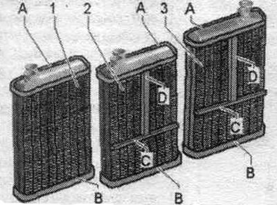
1. Heat exchanger for cars with Basis air conditioning system.
2. Heat exchanger for cars with Comfort air conditioning system.
3. Right-hand drive.
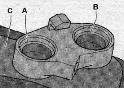
Check the heat exchanger seals; use only heat exchangers with undamaged and securely bonded seals. On vehicles with the Comfort air conditioning system, it is possible to set different temperatures for the right and left sides, as well as behind the rear seats; seals "C" and "D" separate the air ducts in the air conditioner for the left and right sides. The heat exchanger has a color marking where seal "C" should be glued. Glue seal "D" to the center of the heat exchanger, as shown in the figure. The "C" seal comes in different lengths (short version, shown in the figure, or long version for the entire length of the heat exchanger). If the heat exchanger is supplied with a long strip of sealing material "C", stick it around the perimeter of the heat exchanger. An incorrectly glued seal may shift during installation. If the seal is damaged or improperly installed, cold air may enter the heat exchanger; in vehicles with a Comfort air conditioning system, clean insulation may not be provided in various areas. With heat exchanger "A" removed (through the heat exchanger shaft) check the air conditioner and evaporator "F" for contamination. Remove any dirt or leaked coolant from the air conditioner (for example, after removing a leaky heat exchanger). Check the cleanliness and integrity of both connections "A" and "B" of heat exchanger "C". Lightly lubricate both connections "A" and "B" of heat exchanger "C" with silicone grease.
Lightly wet the new "D" seals (supplied with a heat exchanger) OZ (or lightly lubricate with silicone grease). Place new seals "D" on both coolant pipes "E" and "F" to the heat exchanger.
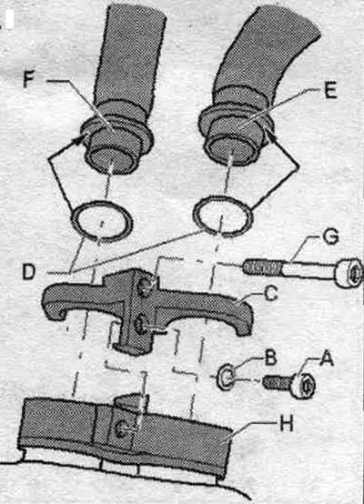
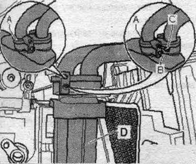
Insert heat exchanger "A" into the air conditioner. Support the heat exchanger "A", for example, with a plastic wedge "B" to the central tunnel "C" so that it does not fall down when the coolant pipes are inserted.
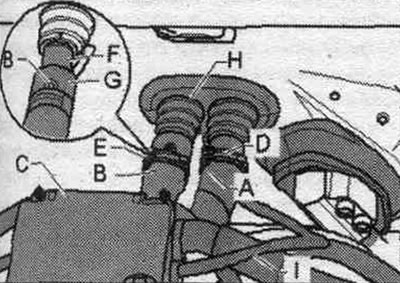
Screw in the long "G" bolt (with M5 thread), according to the figure, insert both coolant pipes "E" and "F" with seal "D" into the heat exchanger pipes on the connecting flange "H" and press them in until they stop. When inserting coolant pipes "D" and "E" into the heat exchanger pipes, do not skew them. Check the fit of seals "C" between coolant pipes "D" and "E" and the connections on connecting flange "B" of heat exchanger "A".
Secure both coolant pipes "E" and "F" with bracket "C" to the heat exchanger connecting flange "H." Bolt "G" is required for ease of installation; it should be removed after the bracket is installed. Insert bolt "A" with washer "B" and tighten bolt "A". Tightening torque of bolt "A" is 2.5 Nm. Remove bolt "G". Check the position of lining "H" in the bulkhead of the engine. compartment. Properly connect the coolant hoses to the heat exchanger, observing the markings.
A. Direct feed from the cyl. head.
B. Return line to the coolant pump
Attach coolant hose "A" to the coolant pipe to the heat exchanger (observe markings) and secure it with clamp "D". Place coolant hose "B" on coolant pipe "F" to the heat exchanger, without blocking air hole "G". Remove the hose clamp from coolant hose "A". Pour coolant into the expansion tank. Carefully pump, for example, with a hand pump of a system tester. cooling "VAG 1274", coolant from expansion. tank into the heat exchanger. After the coolant begins to flow out of the air. hole "G", place coolant hose "B" according to the marking on coolant pipe "F". Secure coolant hose "B" with clamp "E" in the marked place. Remove the hose clamp from coolant hose "B". If necessary, add coolant to the expansion tank. The cooling system is now completely bled. If for some other reasons in the system. there is still air in the cooling system, so it is necessary to bleed it again after installing all the elements.
Check the heat exchanger connections for leaks
Carefully increase the pressure in the cooling circuit using, for example, the hand pump of a system tester. cooling "VAG 1274/". Check the coolant circuit for leaks, especially the connection between the pipes and the heat exchanger. When bleeding the coolant circuit, it is necessary to completely remove air from the heat exchanger. If air still accumulates in the heat exchanger, customers may complain of insufficient heating power in winter or different air temperatures at the outlet of the deflectors with the same adjustment in normal mode. Depending on the vehicle's equipment and engine, heat insulation may be installed on the coolant hoses; these should not be damaged and should be reinstalled after completion of the work. Install all removed elements in reverse order. (preliminary work before removing the heat exchanger). Connect the ground cable of battery "A", following the battery connection instructions. Turn on the ignition. Perform basic setup and diagnostics of the climate control system actuators.
Text provided by the online resource AUDIMANUAL.ru