Repair Chevrolet Repair Toyota Repair Honda Repair AvtoVAZ Repair Mercedes-Benz Repair BMW Repair Opel
Home  |  Contacts  |  Sitemap  |    
English Русский
Български
Беларускі
Український
Српски
Hrvatski
Română
Polski
Slovenský
Magyar
AudiManual.ru


  • AUDI 80
  • AUDI 100
  • AUDI A3
  • AUDI A4
  • AUDI A6
  • AUDI A8
  • AUDI Q
  • OTHER
  • ARTICLES
B8 (2007-2015) B7 (2004-2008) B6 (2000-2006) B6 (2000-2006, petrol) B5 (1994-2001) B5 (1994-2001, petrol)

Forced exhaust ventilation of the passenger compartment: inspection, removal and installation (Audi A4 B8)

  • Home
  • Audi A4
  • B8 (2007-2015)
  • Body
  • Heating and air conditioning
  • Forced exhaust ventilation of the passenger compartment: inspection, removal and installation
            0
Table of contents: Ventilation frames of forced exhaust… ↓ Checking, removing and installing… ↓
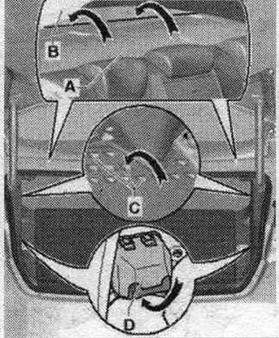
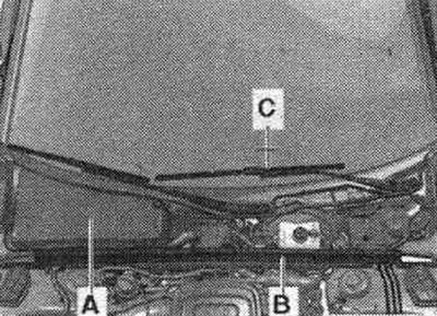
On the Audi A4 sedan, the exhaust ventilation of the passenger compartment is carried out through an opening located between the rear window "B" and the shelf "A" (body), in the luggage compartment. From the trunk, air flows through the exhaust splines "C" into the space between the body and the trunk lining to the exhaust frame "D".

On the Audi A4 sedan, the exhaust ventilation of the passenger compartment is carried out through…


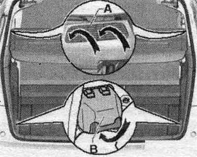
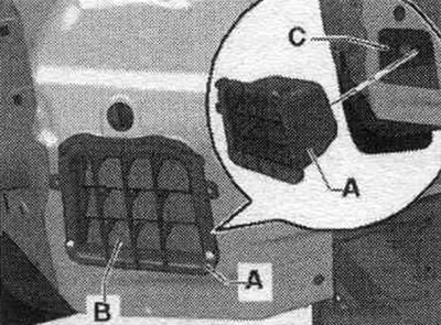
On the Audi A4 Avant, air flows through the left and right exhaust grilles "A" installed in the side trim into the area behind the side trim of the trunk. From there it then goes to the exhaust frame "B".

On the Audi A4 Avant, air flows through the left and right exhaust grilles «A» installed in the…


To ensure forced ventilation. one ventilation frame "A" is built into the ventilation opening "C" of the body on the left and right. The ventilation frames are forced-exhaust ventilators. "A" are removed and installed from the outside (with the bumper cover removed).


To ensure forced ventilation. one ventilation frame «A» is built into the ventilation opening «C»…


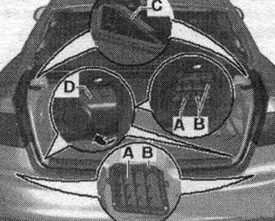
There are different types of ventilation. forced ventilation frames. "A" for vehicles with and without a noise-insulating cover "D". The installation of the noise-insulating cover "D" depends on the vehicle version. For vehicles with a high-voltage system (hybrid vehicles), you may have to remove the second battery "A1" to access the left soundproofing cover "D".

There are different types of ventilation. forced ventilation frames. «A» for vehicles with and…


Checking the ventilation. holes in the trunk trim


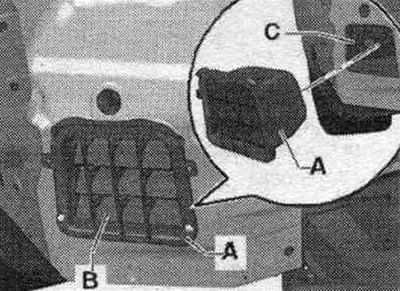
Check the air duct patency through the ventilation frame of the trunk trim on the left and right "C" and behind the trunk trim to both vents. "A" frames in the luggage compartment (left and right). For perfect operation of the exhaust fan. it is not permitted to block the ventilation frames in the right and left side trim of the trunk "C" compartment. Blocked ventilation frames of the trunk trim "C" or clogged air ducts leading to the ventilation. frames "A" may cause fogging of the glass.


Checking the ventilation. forced exhaust ventilation frames. from the inside


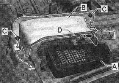
Remove the right and left side trim covers of the trunk. Check the left and right ventilation frames "A" for patency. The sealing edges "B" in ventilation frames "A" should move freely and close automatically. glued seals. "B" edges may cause glass fogging. On cars with acoustic cover "D" make sure that the air duct under the acoustic cover is. the "arrow" cover to the ventilation frames "A" was not blocked by foreign objects. Blocked or clogged air ducts leading to the vent. frames "A" may cause fogging of the glass. To compact. edges "B" are closed correctly, ventilation frame "A" must be installed correctly.

Remove the right and left side trim covers of the trunk. Check the left and right ventilation…


Ventilation frames of forced exhaust ventilation. outside: inspection, removal and installation


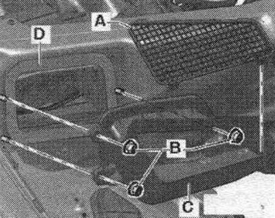
Remove the rear trim. bumpers. Check the left and right ventilation frames "A" for patency and the functioning of the seals. edges "B". Glued seals. "B" edges may cause glass fogging. To compact. edges "B" are closed correctly, ventilation frame "A" should be installed in only one position. The picture shows the ventilation frame "A" with the rear removed. bumper trim. When installing, the ventilation frame "A" should be pressed into the hole in the rear ceiling until all fasteners are securely fixed.


Checking, removing and installing the air intake duct


Turn off the ignition. Remove the water drain box cover and/or water baffle plate (various designs).

Turn off the ignition. Remove the water drain box cover and/or water baffle plate (various designs).


Depending on the vehicle version and the installed water drainage box cover, another additional cover with water drainage "B" may be installed on the fresh air intake channel "A".

Depending on the vehicle version and the installed water drainage box cover, another additional…


Remove both windshield wiper arms (only for vehicles where the fairing and the air intake duct housing on fairing "A" are one piece). Remove the rubber seal "B" on the left as much as necessary. Remove the air intake duct cover on the fairing "A" or the fairing (various designs). If necessary, carefully detach the fairing from the windshield frame mount "C".

Check the correct installation of the fairing "A" and for damage. Check the seals between the fresh air intake duct housing "A," the fairing, and the windshield crossmember "C" for damage and proper installation. These gaskets prevent water from seeping between the windshield crossmembers and through the fairing into the air conditioner intake duct.


Removal and installation


Carry out preliminary work.

Carry out preliminary work.


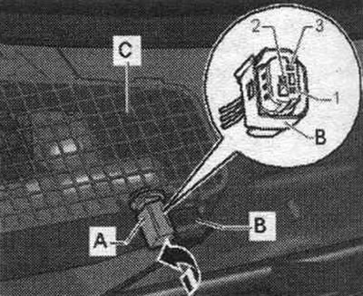
If present, disconnect connector "B" from "G238"/"G657" (various designs). The supply air suction shaft "C" is available in different designs (with or without a mount for "G238" "A", front or side mount), ensure correct design.

If present, disconnect connector «B» from «G238»/«G657» (various designs). The supply air suction…


If present, unscrew the "C" bolts (tightening torque 3 Nm) and remove the gutter cover "B". Unscrew the bolts "B" (tightening torque: 3 Nm). Remove air intake duct "C". Install in reverse order. Before installing the air intake duct "C" and the adhesive seals, inspect them for damage. Replace any damaged seals or the air intake duct "C." During installation, ensure the air intake duct "C" and the corresponding gasket are correctly positioned. If the air intake duct "C" is incorrectly installed, water may enter the air conditioner's intake duct through the seal "D.". Before installing the fairing cover "A", check the fairing and the corresponding cover "A" seals (various designs) and the glass crossbar "C" for damage, if the seal is incorrectly installed or damaged, the cover or fairing can allow water to enter the air intake duct and then into the air conditioner air intake.

The original text of the material can be found on the website: Audimanual.ru
The article was checked by auto expert Timur Bazhenov
This article is available at russian, bulgarian, belarusian, ukrainian, serbian, croatian, romanian, polish, slovak, hungarian

Share information:
Previous articles
Audi A4 B8: Heating and air conditioning
Next articles

Air composition sensor G238/air humidity sensor in the intake…
Exterior Elements, Element Kit (Part 3)
Exterior Elements, Set of Elements (Part 2)
Control system components and adjustment of the climate control…
Components of the climate control and adjustment system in the…
Air conditioner and air intake box components
Removal and installation the air conditioner heat exchanger
Air flow and distribution in the cabin


Similar articles on other Audi car models:
Flywheel/drive disc — removal, inspection and installation Audi 80 B3 (1986-1991, petrol)
Toothed drive belt — removal, inspection and installation Audi 100 C3 (1982-1990, diesel)
Ventilation, heating and air conditioning of the passenger… Audi A3 Type 8L (1996-2003)
Front passenger compartment light — removal and installation Audi A6 C5 Allroad (1999-2005)
Removal and installation of the exhaust system Audi A8 D2 (1994-2002)
Turbocharger — removal and installation Audi Q5 Type 8R (2008-2017)
Removal and installation the exhaust pipe Audi A2 (1999-2005)
Link to this page in different formats


Visitor comments

No comments yet


How much will 39 + 30 =


A4(B8, 2007-2015) 
  • General information
  • Operating instructions
  • Power unit
  • Petrol engines 1.8 l
  • Petrol engines 1.8/2.0 l
  • Petrol engines 3.0 l
  • Petrol engines 3.2 l
  • Fuel system (petrol)
  • Diesel engines 2.0 l (CA*)
  • Diesel engines 2.0 l (CJCB)
  • Diesel engines 2.7/3.0 l
  • Diesel engines 3.0 l
  • Fuel system (diesel)
  • Transmission
  • Manual gearbox 0B1
  • Manual gearbox 0B2
  • Manual gearbox 0B3
  • Manual gearbox 0B4
  • Automatic transmission 0B5
  • Automatic transmission 0B6
  • Automatic transmission 0AW
  • All-wheel drive system
  • Chassis
  • Front suspension
  • Rear suspension
  • Brake system
  • Steering system
  • Body
  • Exterior
  • Interior
  • Seats
  • Doors, locks and windows
  • Security system
  • Heating and air conditioning
  • Electrical equipment
  • Audio system
  • Power devices
  • Equipment and devices
  • Lighting and lamps
  • Electrical circuits
 
A4(B7, 2004-2008) 
  • General information
  • Introduction to manual
  • Troubleshooting
  • Operating instructions
  • Maintenance
  • Power unit
  • Petrol engines 2.0 (ALT)
  • Petrol engines 2.0 (TFSI)
  • Petrol engines 1.8 (MPI)
  • Diesel engines
  • Cooling system
  • Air conditioner
  • Fuel and exhaust system
  • Ignition system
  • Starting and charging
  • Transmission
  • Clutch
  • Manual gearbox
  • Automatic gearbox
  • Drive shafts
  • Chassis
  • Brake system
  • Front suspension
  • Rear suspension
  • Steering
  • Body
  • Exterior
  • Interior
  • Electrical equipment
  • Equipment and devices
  • Lighting and signaling
  • Windscreen wipers and washers
  • Electrical diagrams
  • Electrical diagrams (since 2007)
 
A4(B6, 2000-2006) 
  • General information
  • Vehicle Description
  • User manual
  • Maintenance
  • Power unit
  • Gasoline engine
  • Diesel engine
  • Lubrication system
  • Cooling system
  • Supply system
  • Injection system
  • Exhaust system
  • Ignition and control
  • Transmission
  • Gear box
  • Clutch and drive shafts
  • Chassis
  • Brake system
  • Car suspension
  • Steering
  • Body
  • Heating and ventilation
  • Exterior (external elements)
  • Interior (internal elements)
  • Electrical equipment
  • Power devices
  • Lighting and appliances
  • Electrical circuits
 
A4(B6, 2000-2006, petrol) 
  • General information
  • Introduction to the guide
  • Car care
  • Power unit
  • Engine repair
  • Lubrication system
  • Cooling system
  • Injection and control system
  • Ignition system
  • Power and exhaust system
  • Transmission
  • Clutch and drive shafts
  • Car gearbox
  • Chassis
  • Suspension and wheels
  • Steering
  • Brake system
  • Body
  • Interior
  • Exterior
  • Electrical equipment
  • Equipment and devices
  • Lighting and signaling
  • Power devices
  • Electrical circuits
 
A4(B5, 1994-2001) 
  • General information
  • Introduction to the guide
  • Car care
  • Maintenance (gasoline)
  • Maintenance (diesel)
  • Power unit
  • Gasoline engines
  • Diesel engines
  • Engine overhaul
  • Cooling system
  • Fuel injection (gasoline)
  • Fuel system (diesel)
  • Exhaust system
  • Ignition system
  • Transmission
  • Clutch
  • Mechanical gearbox
  • Automatic gearbox
  • Drive shafts
  • Chassis
  • Brake system
  • Car suspension
  • Steering
  • Body
  • Exterior
  • Interior
  • Doors, locks and windows
  • Heating and ventilation
  • Electrical equipment
  • Power devices
  • Equipment and devices
  • Electrical circuits
 
A4(B5, 1994-2001, petrol) 
  • General information
  • Vehicle description
  • Maintenance
  • Power unit
  • Engine repair
  • Turbocharging
  • Exhaust system
  • Cooling system
  • Ignition system
  • Fuel system
  • Motronic injection system
  • MPI and MPFI injection system
  • Transmission
  • Clutch
  • Gearbox and shafts
  • Chassis
  • Steering
  • Car suspension
  • Brake system
  • Wheels and tires
  • Body
  • Heating and ventilation
  • Body parts
  • Electrical equipment
  • Fuses and relays
  • Power devices
  • Lighting and lamps
  • Tools and devices
  • Electrical circuits
 
AudiManual.ru © 2017-2026 · Mobile version · Feedback · Sitemap: EN BG BY UA RS HR RO PL SK HU · Site search · News and articles
80 B2 · 80 B3 petrol · 80 B3 · 80 B4 · 100 C3 diesel · 100 C3 petrol · 100 C3 · 100 C4 petrol · 100 C4 · A3 Type 8L · A4 B5 petrol · A4 B5 · A4 B6 petrol · A4 B6 · A4 B7 · A4 B8 · A6 C4 · A6 C5 · A6 C5 Allroad · A8 D2 · Q5 Type 8R · Q7 Typ 4L · Audi A2 ·
This site uses cookies 🍪. Click the button to accept this fact.