



Table of contents: Elements outside the cabin ↓ Exterior Elements, Set of Elements 1 ↓ Removal and installation the outside… ↓
Note: If in climate. there is a malfunction in the installation, the fault memory readings should be read. control panel and climate control indicators, settings, used Climatronic "J255". If the indication of memory reading is faulty. on other used ones it is also necessary to consider the faulty memory. of this used (e.g. used on-board network "J519", center, used comfort system "J393"), certain elements of the climate control system (e.g. compressor control valve of the climate control system "N280", temperature and refrigerant pressure sensor "G395") are no longer directly controlled by the used Climatronic "3255" and climate control system display / their measured values are no longer processed directly by the used Climatronic "J255" and climate control system display. If the malfunction is not displayed, read the measured value block pan. climate control and indication. installations, used Climatronic "J255", the faulty component can be controlled using the Actuator Diagnostics function. When conducting el. checks using the function Gefuehrte Fehlersuche/guided troubleshooting. you can find instructions on the functions that need to be tested. Temp dependent. resistance values on different temperature sensors. are presented in tables that can be called up using the Guided Fault Finding function. Electrical testing of various actuator motors is described in the Guided Fault Finding function. Upon completion of the repair, perform the following tasks. Query memory faulty. climate control and display module, installation, used Climatronic "J255" and remove possible displayed faults. Check the coding of the climate control and display module. installation, used Climatronic "J255". Check the adaptation of the climate control and display module. installation. used Climatronic "J255". Perform basic climate control settings. installations.
Elements outside the cabin
(all performances)
Note: Depending on the vehicle production period, certain versions may have connecting elements integrated into the refrigerant lines (currently not provided, the question of use is open). These connecting elements, like the pipes, may be unscrewed and removed from various units only if the refrigerant circuit is empty. For vehicles with a 6-cylinder petrol engine and other engines with certain additional equipment (for example, in a car with a start/stop system), but without additional equipment, an independent heater is installed with a coolant circulation pump "V50" (water pump "V36"). Depending on the version of the panel. climate control and indication. a used Climatronic "J255" may be identified as a "V50" coolant circulation pump in the guided troubleshooting, as well as a "V36" water pump. Depending on the interior trim level or production date, the design of the "V50" coolant circulation pump (or "V36" coolant pump) and the pump controls vary. Since 2012 model year, depending on the engine, pumps installed from the start of production are controlled by a 500 Hz signal (500 pulses per second), are gradually being replaced by pumps with 100 Hz signal control. Pumps with 100 Hz signal control are additionally equipped with a diagnostic function and are controlled by a corresponding used one, so it is necessary to take into account the correct matching (the control signal must be supplied only to the corresponding pump).
Exterior Elements, Set of Elements 1
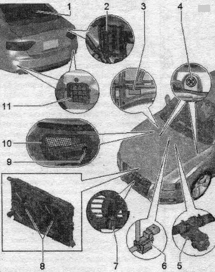
1. Rear heating. glass "Z1": request for rear heating. glass is sent by the climate control and indication module, installation, used Climatronic "J255" through the system. data buses to the center, used comfort system "J393"; rear heating control. glass "Z1" is carried out through the center, used comfort system "J393".
2. Central used system Comfort "J393": rear heating control. glass "Z1" is carried out through the center, used comfort system "J393".
3. Information plate: with information on the type of refrigerant and filling volume.
4. Water drains: in the drainage box there is one drain on the left and on the right.
5. Coolant shut-off valve: Depending on the engine, the shut-off valve is installed in the direct or return coolant line from the engine to the air conditioning heat exchanger; the shut-off valve is currently installed only on vehicles with a 4- or 6-cylinder petrol engine. If an auxiliary heater is installed on vehicles with such engines (as an optional. equipment), then there is no shut-off valve (the coolant shut-off valve of the heating system "N279", installed on cars with an independent heater, takes over this task); the shut-off valve is controlled by means of a vacuum through the coolant shut-off valve of the Climatronic unit "N422".
6. Climatronic coolant supply shut-off valve "N422"; the installation location and design of the Climatronic "N422" coolant shut-off valve varies, depending on the engine and vehicle configuration, it can be installed in the engine. compartment or in a water drainage box; the Climatronic coolant shut-off valve "N422" is currently installed only on vehicles with a 4- or 6-cylinder engine. If an independent heater is installed on vehicles with such engines, then "N422" is not present (the heating system coolant shut-off valve "N279", installed on vehicles with an independent heater, takes over this task).
7. Outdoor temperature sensor. "G17": measured value of the outside temperature sensor. "G17" is rated as used on-board network "J519" and sent via the system. data bus in the control and display panel, used Climatronic "J255".
8. Radiator fan "V7" and radiator fan 2 "V177": radiator fan "V7" and radiator fan 2 "V177" are installed in different versions depending on the vehicle configuration; the command to turn on one or all "V7" fans is transmitted to the air conditioner indicator, used Climatronic "J255", via the data bus system to the corresponding used engine. Then the used engine turns on 1 or all radiator fans (radiator fan "V7" and radiator fan 2 "V177") directly or via the used fan system. cooling -J293.-; check the control signals to the climate control panel, used Climatronic "J255" installation; the corresponding used engine includes, for example, the radiator fan "V7" and the radiator fan 2 "V177" (directly or via the used fans "J293") steplessly at the required power (depending on the engine type).
9. Air composition sensor "6238"/air humidity sensor in the supply duct "G657": various versions; measured value "G238"/"G657" the data is processed by the used on-board network "J519" and transmitted via the data bus to the used Climatronic "J255" control and display panel. The used Climatronic "J255" control and display panel is activated, for example, when a recirculation command is given and no conditions for shutdown exist. Various versions are installed, depending on the date of production of the car and the version of the climate control system (Basis or Comfort). When performing climate control. installation of Basis before the gradual re-equipment of vehicles from the 2012 model year "G657"/"G238" not installed, with this conversion "G657" is installed without "G238" (body color: black). In the Comfort version, before the gradual re-equipment of the vehicle version from the 2012 model year, the "G238" was installed without the "G657"; from this re-equipment, the "G657" is installed with the "G238" (body color is brown). The air composition sensor "G238" without "G657" is installed only in vehicles with the Comfort air conditioning system (from the start of production to re-equipment). Since the 2012 model year, there has been a gradual change in performance. On cars that were produced before the conversion, if there is air conditioning, the Comfort version is equipped with "G238" (not installed with Basis).
10. Fresh air intake duct with grille: check the fairing with the fresh air intake casing for proper installation and for damage, check the seals between the fresh air intake duct casing, the fairing and the glass crossbar for damage and for proper installation; these gaskets prevent water from seeping between the glass cross supports and through the fairing into the air conditioning intake duct; pay attention to the correct position of the intake grille. The intake filter prevents foreign objects from entering the air intake shaft. Climate control systems: Depending on the version, vehicles for countries with high dust content in the air may have a filter instead of a grille, preventing dust and sand from entering through the intake fan. Depending on the vehicle version and the installed water drainage box cover, another additional cover with a water drainage system may be installed on the fresh air intake channel.
11. Forced ventilation: one forced exhaust vent is installed under the rear bumper. left and right; the sealing edges of the ventilation frame must move freely and close automatically: for the perfect operation of the ventilation. the interior trim of the trunk should not block the air ducts.
Placement, control and operation of the coolant shut-off valve of the Gimatronic "N422" unit and the coolant shut-off valve
The installation location and design of the Climatronic unit coolant shut-off valve "N422" "B" and the coolant shut-off valve "A" depends on the engine, vehicle configuration and time of manufacture. This is the drawing the "N422" "B" version for the 6-cyl. FSI engine, which was installed at the beginning of production, is shown. Here, the "N422" "B" version 1 is installed in the cylinder head area. The Climatronic unit coolant shutoff valve "N422" was installed, for example, at the beginning of production on vehicles with a 6-cylinder FSI engine. Installation on other engines was gradually implemented in the 2008 model year. The exact application depends on the vehicle's configuration and production date. For example, if a vehicle is equipped with an independent heater, then "N422" "B" and shut-off valve "A" are not installed. The heater coolant shut-off valve "N279" installed in vehicles with an independent heater performs the functions of the independent heater.
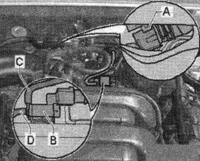
When installing "N422" "B", ensure that the low pressure hoses are connected correctly. In version 1, port 3 "C" of the low-pressure hose is connected to shut-off valve "A." Port 2 "D" supplies vacuum from the engine. In version 2, connection 3 of the low-pressure hose "C" is connected to shut-off valve "A." Vacuum from the engine is supplied through connection 2 "D.".
Note: This illustration shows, for example, the arrangement for a 4-cyl. diesel engine model year 2009. Ventilation of the vacuum reservoir of the shut-off valve "A" after completion of control is carried out, for example, in version 2 "N422" "B" via the branch pipe 1 located under the cap "E". Depending on the version, the vacuum hose "C" (to the shut-off valve "A") may be marked with a white mark at the connection point. Ensure the vacuum hoses "N422" "B" are correctly positioned. Reversed vacuum hoses can cause the cabin heater to malfunction.
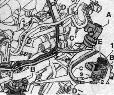
"N422" "B" receives short control signals at certain intervals (for example, every 10 engine starts) from the control panel and indication, used Climatronic "J255" for checking the operation (without the need for a function). If the vacuum hoses are reversed when connecting to "N422" "B," control signals are briefly sent to coolant shutoff valve "A." After the control signal is removed, a vacuum remains in the vacuum reservoir of coolant shutoff valve "A" for an indefinite period of time. In this case, shut-off valve "A" does not open. When shut-off valve "A" is closed, coolant cannot flow to the heat exchanger and the air conditioning system does not heat. Coolant shut-off valve for Climatronic "N422" by reg. climate, installations, for example, receive a control signal only when for climate. the unit's operating mode is set to OFF. The engine speed must be less than 5000 rpm and the coolant temperature less than 90°C. By blocking the coolant circuit to the air conditioning heat exchanger, the unit accelerates engine warm-up when the coolant is cold. If the vacuum hoses are incorrectly connected, the engine constantly draws a small amount of fresh air through port 1 "N422". This can additionally. may cause problems with engine idle speed control and may cause a fault to be entered into the used engine's memory.
Note: For vehicles with 6-cylinder FSI engine (currently not available on the 6-cyl. TFSI engine) and on other engines with certain additional equipment (for example, in a car with a start/stop system) but without additional equipment, an independent heater is installed with a coolant circulation pump "V50" (water pump "V36"). Depending on the version of the panel. control and climate control, installation, used Climatronic "J255" can be designated as coolant circulation pump "V50" in the guided troubleshooting, as well as water pump "V36". Control "V50" ("V36") and "N422" depends on the vehicle's configuration and production date. The "V50" coolant circulation pump (water pump "V36"), depending on the production date, is controlled via the "J160" circulation pump relay (via the same output as the "N422" Climatronic coolant shut-off valve) or directly from the used Climatronic "J255" climate control unit and display, which is gradually installed with the mod. 2009. Pay attention to the correct execution of the used climate control system and indication, installation, used Climatronic "J255" and correct coding and adaptation. On vehicles with a "J160" circulation pump relay (for example, on a 2008 model year car) management is carried out "V50" ("V36") with the ignition on, if the Climatronic coolant shut-off valve "N422" is not controlled correctly (e.g. when the temperature mode is warm on the panel. climate control and display, installation, Climatronic unit "J255"). On vehicles without the "J160" circulation pump relay (gradual implementation from mod. year 2009) coolant circulation pump "V50" "V36" with the ignition on, depending on the temperature. Coolant and settings for used and climate control indicators, settings, used Climatronic "J255" was controlled directly from this unit. On vehicles where the coolant circulation pump "V50" "V36" and the coolant shut-off valve for Climatronic "N422" are controlled directly from the control panel. control and climate control system, installation, used Climatronic "J255", these units still have faults in the panel. controls and climate control indicators, installations, used Climatronic "J255". Therefore, the design should be taken into account. j255 coding and adaptation. Depending on the interior trim or production date, the design of the V50 coolant circulation pump (V36 coolant pump) and pump control differ.
Removal and installation the outside temperature sensor. "G17"
Note: Value measured by the outside temperature sensor. "G17", is processed by the used on-board network "J519" and with the help of the system. the data bus is transmitted to the used climate control system and display, used Climatronic "J255" (and used in the instrument cluster "J285"). On vehicles in which "G17" "A" with bracket "B" is installed on the decorative grille above the amplifier, as a result of this location of "G17" under certain conditions it may happen that an increased temperature value will be output (due to heat radiation from the radiator of the system. cooling and condenser, for example, on cars of the 2008 model year). Therefore, in the 2009 model year, the location of "G17" "A" gradually changes, "G17" is installed with a modified bracket "C" slightly in front (closer to the radiator grille) and below the amplifier "D". On cars in which the "G17" "A" with bracket "B" is installed on the decorative grille above the amplifier, there may be complaints about an increased measured temperature value. Install the "G17" "A" with a modified bracket "C" slightly forward (closer to the radiator grille of the system. cooling) and below the "D" amplifier. Depending on the design of the wiring, it may be necessary to extend it further — Electronic parts catalog. Bracket "C" is attached to the amplifier "D" (for this, if it is not available, you need to drill a hole with a diameter of 7 mm under the amplifier "D").
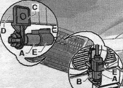
Removal
Turn off the ignition. Removing the top panel cover. Disconnect the temperature sensor connector "E". "A" and unfasten the sensor from the bracket ("B" or "D"). Depending on the vehicle's configuration, it may be necessary to remove the bumper to remove "G17" "A" from the bracket "C" installed under the amplifier "D" (if, for example, on a vehicle with additional radiators, "G17" is inaccessible from above). After installation, query the fault memory. used and indicators, used Climatronic "J255" (and used in the instrument cluster "J285") and delete possible displayed faults.
The original version is on the portal: audimanual.ru