
Table of contents: Air conditioning elements and air… ↓ Elements of the air conditioner and… ↓ Cooling pipe front. box on the air… ↓ Removal and installation the air… ↓ Disassembling and assembling the air… ↓
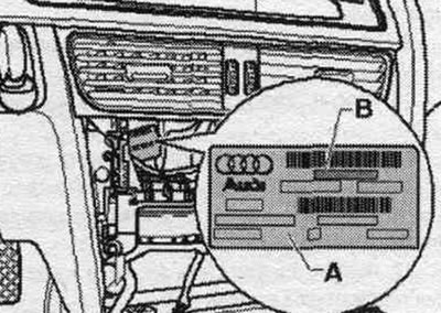
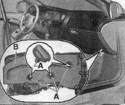
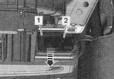
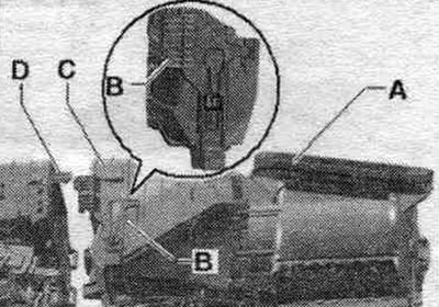
Note: Different climate versions. the installation can be identified from the outside by the part number "B" on the "A" sticker. The "B" part number on the "A" sticker can be seen, for example, with the CD changer removed (depending on the vehicle configuration).
Air conditioning elements and air intake box of the Basis version
Since 2012 model year gradually (implementation depending on the vehicle version) modified air conditioners are starting to be installed (air conditioner with part number 8T_820 005). With the use of these air conditioners, other actuator motors are also installed; various versions of actuator motors are currently installed with both versions of the air conditioner (mixed installation is not allowed).
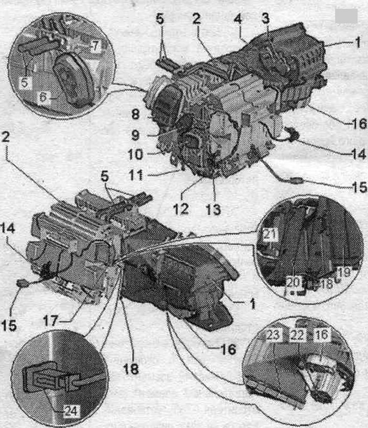
1. Air intake box: different versions (with or without nipple for front cooling. box). From 01.2008, air conditioning units equipped with additional equipment will be gradually introduced. cooling pipe for front. box. This pipe is on a car without a system. cooling lane. the box is closed with a plug. Since 2012 model year gradually (installation depending on the vehicle version) the modified J126 fresh air fan control units (and V2 fresh air fans, control and display panel, used Climatronic J255, and air conditioners with part number 8T_820 005) are installed. Along with the J126 and air conditioner, the air intake box has also been modified. Ensure proper installation and alignment of these components.
2. Air conditioner with evaporator (basis performance): remove only when the air conditioning circuit is empty, deliver the car to a workshop that has the necessary equipment and trained qualified personnel; clean the evaporator of the air conditioning system using the ultrasonic device for cleaning air conditioning systems "VAS 6189".
3. Air recirculation flap servo drive "V113".
4. Air intake flap servomotor "V71".
5. Heat exchanger pipes.
6. Expansion valve.
7 Bushing: For insulating the hole for refrigerant pipes through the rear wall of the water drain box.
8. Cover of refrigerant pipes to the evaporator.
9. Defrost flap servomotor "V107".
10. Actuator of the space damper. for legs "V261".
11. Condensate drain connection on the left (from the side drives.): check the condensate drain, remove and install the condensate drain hose.
12. Executive el. motor of air temperature control flap "V68".
13. Temperature sensor, air vent space. for feet "G192": the footwell air temperature sensor "G192" is installed in the left footwell deflector.
14. Temperature sensor, central air vent "G191": the temperature sensor, central air vent -G191 - is installed in the air duct to the central air vent of the front panel.
15. Connecting the used climate control system and indication unit for Climatronic "J255" to the air conditioner wiring harness.
16. Used supply fan "J126".
17. Executive drive of the central deflector "V102".
18. Right condensate drain connection (front side. passenger): check the steam trap, remove and install the steam trap hose.
19. Evaporator.
20. Heat exchanger system. heating.
21. Additional heating element. heater "235"/cellular element: additional heating element. the "Z35" heater is installed on vehicles with diesel engines and on vehicles with certain gasoline engines; on vehicles with petrol engine (without additional heating element. heater "Z35") to fill the free space. a cellular element is installed (this ensures the same air flows in the air conditioner with additional heating element. heater "Z35" and without it); if a diesel vehicle is equipped with an independent heater as an additional option. heater (additional equipment), then an additional heating element is not used here. heater "Z35", and the cellular element (the question of use remains open); check the operation of the heating element for additional. heater "Z35".
22. Supply fan "V2".
23. Cabin filter: observe replacement intervals; various designs with and without activated carbon filter.
24. Temperature sensor, refrigerant at the outlet of the evaporator "G263".
Elements of the air conditioner and air intake box of the Comfort version
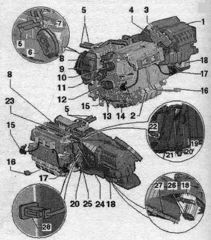
1. Air intake box: different versions (with or without nipple for front cooling. box).
2. Air conditioner with evaporator (comfort version): remove only when the air conditioning circuit is empty, deliver the car to a workshop that has the necessary equipment and trained qualified personnel; clean the evaporator of the air conditioning system using the ultrasonic device for cleaning air conditioning systems "VAS 6189".
3. Air recirculation flap servo drive "V113".
4. Air intake flap servomotor "V71".
5. Heat exchanger pipes.
6. Expansion valve.
7. Bushing: for insulating the hole for refrigerant pipes through the rear wall of the water drain box.
8. Executive el. motor of the left temperature flap "V158".
9. Cover of refrigerant pipes to the evaporator.
10. Executive electric motor of the left central deflector "V110".
11. Defrost flap servomotor "V107".
12. Execution drive of the space damper. for legs on the left "V108".
13. Condensate drain connection on the left (from the side drives.): check the condensate drain, remove and install the condensate drain hose.
14. Executive el. motor for rear air temperature control flap "V137".
15. Temperature sensor, air vent. for left footwell "G261": the left footwell air supply temperature sensor "G261" is installed in the left footwell deflector.
16. Connecting the used climate control system and indication, used for Climatronic "J255" to the air conditioner wiring harness.
17. Temperature sensor, air outlet in the right footwell "G262": the temperature sensor, supplied air in the right footwell "G262" is installed in the footwell deflector. for the legs on the right.
18. Used supply fan "J126".
19. Evaporator.
20. Right condensate drain connection (front side. passenger): check the steam trap, remove and install the steam trap hose.
21. Heat exchanger system. heating.
22. Additional heating element. heater "235"/cellular element: additional heating element. heater "Z35" is installed on diesel vehicles and on vehicles with certain petrol engines: on vehicles with petrol engine (without additional heating element. heater "Z35") to fill the free space. a cellular element is installed (this ensures the same air flows in the air conditioner with additional heating element. heater "Z35" and without it); if a diesel vehicle is equipped with an independent heater as an additional option. heater (additional equipment), then an additional heating element is not used here. heater "Z35", and the cellular element (the question of use remains open); check the operation of the heating element for additional. heater "Z35".
23. Executive el. motor of the right temperature flap "V159".
24. Executive electric motor of the right central deflector "V111".
25. Execution drive of the space damper. for the feet on the right "V109".
26. Supply fan "V2".
27. Cabin filter: observe replacement intervals; various designs (with and without an absorbent filter).
28. Temperature sensor, refrigerant at the outlet of the evaporator "G263".
Cooling pipe front. box on the air intake
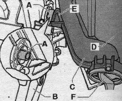
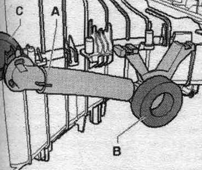
On vehicles with additional equipment, the front cooling system. the cooled air is supplied to the glove box from the climate control unit through the glove air cooling pipe "C" and through the air duct "A" located on the air intake. The air duct leading to the glove compartment is sealed with a foam polymer seal "B". On vehicles with a front-end cooling system. box take into account the correct execution of the first. box.
Removal and installation the air conditioning intake box
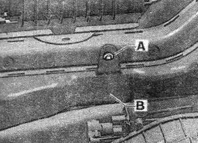
Turn on the ignition. Set the air flow direction on a used Climatronic "J255" climate control unit and indicators, on a DEF (to the windshield). Move the passenger compartment and seat to the rearmost position. Turn off the ignition. Remove the glove compartment. Removing the deflector space. for the right footwell (front side. passage). Remove the threaded clamp "A" and the noise-insulating mat "B".
Remove screws "A". Disconnect the air duct to the right front panel deflector from the front panel cross member (do not remove). Air duct from air. channel "B" is secured to the right deflector of the front panel with 2 bolts; to loosen it, remove only the bolt that is screwed from below into the crossbar of the front panel and is accessible. Remove the air duct "B" to the front panel deflector on the right (front side. passage.).
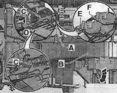
Remove the A-pillar "C" trim and the "B" mount. Disconnect the "A" connector from the used "J126" intake fan.
If available, remove the used headlight corrector "J431" "1" (or the used adaptive lighting and headlight corrector "J745") and the corresponding mounting frames. Remove the "V2" supply fan. The air intake box in the air conditioner can also be removed and installed with the "V2" supply fan installed, due to limited space. it is still advisable to remove "V2" from the installation (more freedom of movement will be achieved when removing and installing the air intake box).
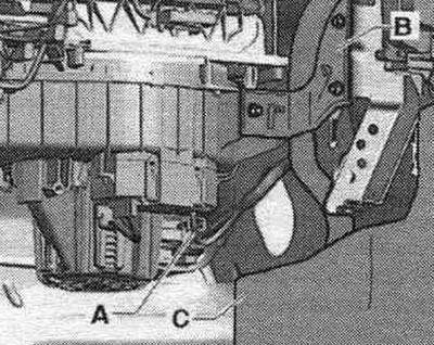
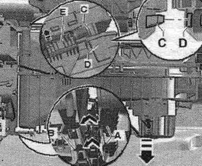
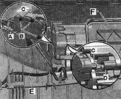
Remove cables "A" from the air intake box mounting points. Open the fastening "C" (between the air conditioner and the air intake box "B"), for example, using a screwdriver "D" (lift slightly and pull in the direction of the arrow). Pull the air intake box "B" (after opening the fastening "C") from the right down (in the direction of the arrow). Mark the plugs to the air intake flap actuator "V71" "E" and "F" to the recirculation flap actuator "V113" (to avoid confusion with other plugs) and disconnect them from the servomotors.
Remove the upper air conditioner tab "E" from the air intake box mount "D". Release both lower mounting points between the air conditioner "B" and the air intake box "A". Remove the air intake box.
Installation
Installation in reverse order. Inspect and, if necessary, clean evaporator "A" and the air conditioning duct to evaporator "B." Inspect and, if necessary, clean the cabin filter and the air intake duct to air conditioning unit "C." Check the integrity of the round groove on air conditioning unit "D" and the round chamfer on air intake box "E." If the groove or chamfer is damaged, fill the damaged area with, for example, silicone sealant D176 001 A3. Air may leak through this area during operation of the air conditioning system, causing noise.
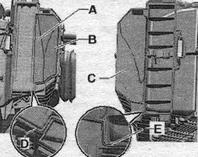
Before installing the air intake box "C," check the integrity of the seal on the outside air intake shaft "A." Replace any damaged seal if necessary. Check the position of the lock, only if the stopper "B" is in the position corresponding to the figure, you can connect the air intake box "C" and the air conditioner "D".
Connect the connectors to the air intake flap actuator "V71" "E" and the recirculation flap actuator "V113" "F" according to the markings. Insert both lower tabs of the air intake box "A" into the air conditioner mounting points "B." Lift the air intake box on the right side until the upper tab of the air conditioner "C" engages the air intake box mount "D," then press both elements together. If the "E" retainer moves forward during installation, it will not be possible to compress both elements. When installing, make sure that you do not pinch other elements and that the chamfer on the air intake box fits completely into the groove on the air conditioner. Move clamp "C" against the arrow (thereby securing the air conditioner to the air intake box "B"). Install cables "A" into the air intake box mounting points. When laying cables, ensure that they do not touch the moving parts of the actuator motors.
All removed elements are installed in the reverse order. Turn on the ignition. Perform basic setup and diagnostics of the climate control system actuators. In this car, the actuator electric motors have an electronic part; the new electric motor stores its position on the air conditioner only during the basic setting, after which it is ready to execute commands from the used and climate control display, settings, used Climatronic "J255" (currently, all electric motors are identical). During the basic setup, the actuator motors are allocated and programmed according to the distribution in the series connection. If this sequence does not correspond to the specified parameters, the servomotors store incorrect information, after which the control of the dampers will be incorrect (schematic diagram of the climate control system). If you are not sure that both control motors, the air intake flap control motor -V71- and the recirculation flap control motor "V113", are correctly connected to the wiring. You can check the controls using the Climate Control Actuator Diagnostics function. With the glove compartment removed, the "F" recirculation flap is visible. Query the fault memory. control panel, and climate control indicators, settings, used Climatronic "J255" and, if necessary, erase the displayed faults.
Disassembling and assembling the air conditioning intake box
Remove the air intake box.
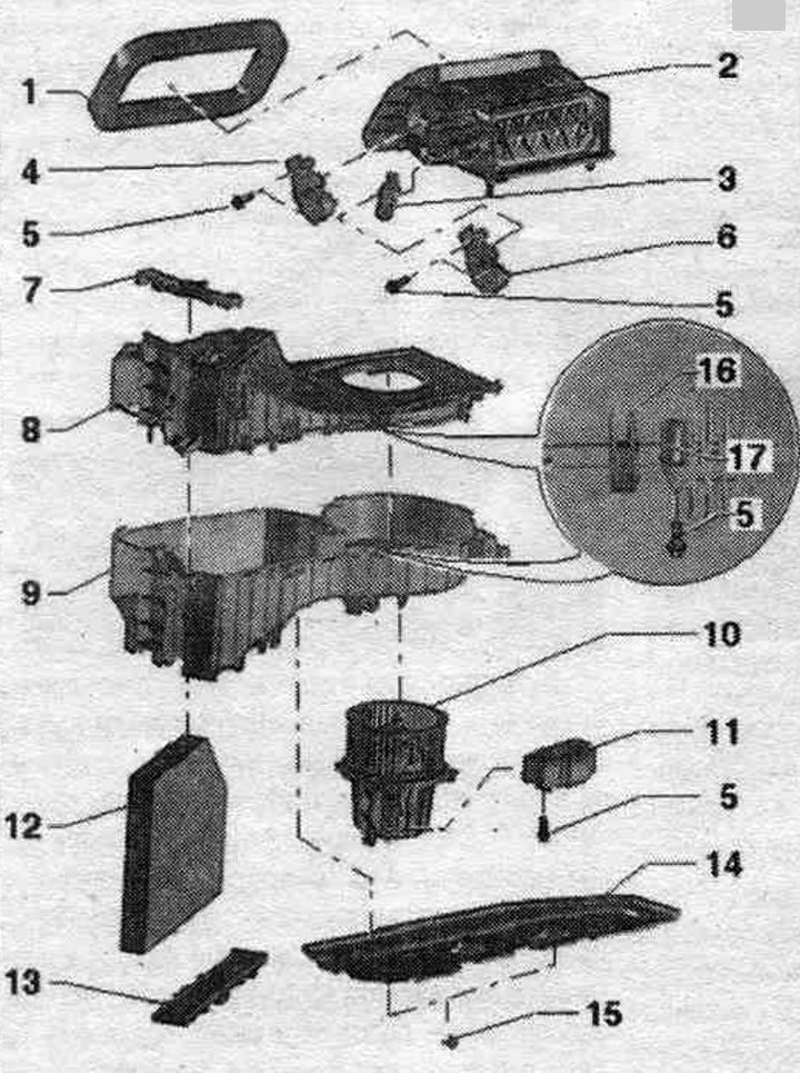
1. Foam polymer seal: for insulating the fresh air intake shaft to the vehicle, glued to the air intake shaft.
2. Air intake shaft: with air intake, supply air and recirculation damper; do not disassemble into parts.
3. Disc cam: via 2 levers, drives the air intake and fresh air flaps; lightly lubricate the camshaft guides and the camshaft lever journals (for example, solid lubricating paste -G 000 150-).
4. Air intake flap servomotor "V71".
5. Bolt.
6. Air recirculation flap servo drive "V113".
7. Clamp: for connecting the air intake box to the air conditioner.
8. Upper part of the air intake box: do not disassemble; if one of the tongues breaks or one of the welding points breaks off, both body elements can be connected with bolts; different versions (with and without nipple for front cooling. box), in this drawing the version shown is without a pipe for cooling the front. drawer. Depending on the design of the original part, the upper and lower parts are connected with bolts at the bolting points, or the upper part is welded to the lower part at various points. The upper and lower parts of the air intake box are currently supplied as separate parts as spare parts. Assemble both parts, then connect them with bolts at the designated points.
9. Lower part of the air intake box: do not disassemble; if one of the tongues breaks or one of the welding points breaks off, both body elements can be connected with bolts; since the 2012 model year, a modified version has gradually begun to be installed; please take into account the instructions for this part of the air conditioner and the air intake box of the Basis version.
10. Supply fan "V2".
11. Used supply fan "J126".
12. Cabin filter: observe replacement intervals; various designs (with and without an absorbent filter).
13. Cabin filter cover.
14. Insulation mat: various designs depending on the design of the supply air fan "V2".
15. Screw clamp.
16. Fasteners on the top of the air intake box.
17. Make-up point.
[Read the original source on the website AUDImanual]