
Note. Perform guided troubleshooting on the auxiliary heater. Guided troubleshooting of the auxiliary heater is carried out, for example, using diagnostics. complex -VAS 5051/- or tester -VAS 5052-. Guided troubleshooting of the auxiliary heater only works when the ignition is on (diag. The data bus interface -J533- is only active when the ignition is switched on). After switching the auxiliary heater to diag. mode, you can continue to perform guided troubleshooting even when the ignition is switched off. The auxiliary heater is available in different versions (Autonomous heaters with the number 8K0.xxx.xxx cannot be installed on the Audi Q5 and are not installed), therefore take into account the correct match when replacing the auxiliary heater. From 10.2010, the gradual use of autonomous heaters with part number 4xx xxx xxx begins. This version of the auxiliary heater can be installed in a service center on a vehicle initially equipped with an auxiliary heater with part number 8R0 xxx xxx or 8K0 xxx xxx. Since the individual components differ for different versions of the autonomous heater (e.g. 2-pin plug connector for the power supply circuit of the additional control unit. heater -J364-), when replacing individual components of the auxiliary heater, take into account the correct match. When installing an auxiliary heater with part number 4xx xxx xxx, it is necessary to take into account the correct coding for the corresponding vehicle for this version (Various functions are provided depending on the vehicle type coded in the control unit). If the auxiliary heater needs to be replaced, then the coding and adaptation of the auxiliary control unit should be interrogated before removal. heater -J364- via function "Replacing the control unit" in guided troubleshooting (additional control unit heater -J364- integrated in the heater). If, depending on the version of the control unit, additional heater -J364- if the auxiliary heater cannot be switched on on a new vehicle or after installing a new auxiliary heater, component protection may be activated (If, before the first commissioning, for example, a large number of faults were detected simultaneously in production, this fault message is not displayed, although the fault is still present). In this case, the component protection function must be re-adapted, similar to the installation of a new auxiliary heater, by deactivating its activity using the tester in the U4S 5051/Guided Fault Finding mode. The following figure shows the location of components and parts for the Audi A4 or Audi Q5; there are minor differences in the location of components/parts from this figure.
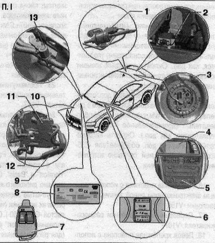
I 1. Metering pump -V54-. Selection of fuel for an autonomous heater. Check the fuel supply volume. Depending on the version of the vehicle in fuel. line to the auxiliary heater, a silencer can be installed in the area of the metering pump -V54- to reduce noise 2. Autonomous heater radio -R64-. There are various versions of the auxiliary heater radio signal receiver -R64-; 3. Fuel supply module with a pipe for extracting fuel for an autonomous heater. Various fuel supply modules, depending on vehicle type (petrol or diesel engine, front-wheel drive or all-wheel drive). After removing and installing fuel components. system, it is necessary to turn on the autonomous heater and let it run for at least 10 minutes at full load to ensure complete removal of air from the fuel. highways; 4. Multimedia interface (MMI). Various control functions for the auxiliary heater and auxiliary ventilation are entered via the MMI and displayed on the corresponding display. Autonomous heater control, MMI (on the menu "Sag"), multimedia interface and the corresponding display indications are described in the corresponding operating instructions. If in fuel the tank is too low on fuel (the fuel gauge needle is in the red zone), it will not be possible to turn on the autonomous heater (tick in the MMI for the function "Immediate activation of the auxiliary heater" and the auxiliary heater icon on the clock does not turn on or goes out immediately); 5. Control and display panel for Climatronic control unit -J255-. Receives control signals via the data bus. When you turn on the auxiliary heater through the function "Timer" or using a remote control, decides in which mode to turn on the autonomous heater (autonomous ventilation or autonomous heater). So that the auxiliary heater can be turned on using the function "Timer" or remote control (keychain), you need to select a higher temperature "Lo" on the control and display panel of the Climatronic control unit -J255-. To ensure that the windows can be cleared of ice as quickly as possible, we recommend setting the display and display unit, Climatronic control unit -J255- to as high a temperature as possible before switching off the ignition. Used and display, the Climatronic control unit -J255- uses the last set temperature in the operation of the auxiliary heater and regulates the temperature in the passenger compartment in accordance with the set temperature. Since the 2010 model year for this vehicle, the start/stop system is offered for certain engines as an additional option. set. On such vehicles, take into account the correct design of the climate control and display panel. Installation of the Climatronic control unit -J255- and the auxiliary heater. On vehicles with an engine start/stop system, the auxiliary heater circulation pump -V55- receives control signals from the auxiliary control unit during the stop function. heater -J364-. The switching request -J364- comes from the climate control and display unit, the Climatronic control unit -J255- via the data bus -V55-. Depending on the selected operating mode ("heater" or "autonomous ventilation") Certain fault messages that have a negative impact on the auxiliary heater/autonomous ventilation mode are not stored in the memory of the auxiliary control unit. heater -J364-. Therefore, if there are complaints about the auxiliary heater, also read the fault memory of the Climatronic control unit -J255- using the VAS 5051 diagnostic system. After replacing the auxiliary heater, ensure that the new auxiliary heater is adapted correctly. When replacing an autonomous heater with the number 8K0 xxx xxx, 8R0 xxx xxx or 4H0 xxx xxx up to the index "A" for an auxiliary heater with part number 4H0 xxx xxx starting with the index "IN" The adaptation for the control signal of the circulation pump -V55- must be activated using the additional control unit. heater -J364- in climate control mode, settings (for an autonomous heater with number 4H0 xxx xxx, starting with the index "IN", this function is disabled). If - V55 - at the request of the climate control and display panel. installation of the Climatronic control unit -J255- from -J364- is not activated on certain vehicle versions (depending on engine and production period) Faults may be reported due to low or insufficient heat output. If in vehicles in which the manufacturer has installed an autonomous heater with the number 4H0 xxx xxx, starting with the index "IN" (installed since 2012 MY), -V55- is activated by the request -J255- from -J364-, this can also lead to a complaint; 6. Display in the instrument cluster. Installed in the instrument cluster. Depending on the version, additional equipment "heater" should be configured via the function "Adaptation" in the control unit in the instrument cluster -J285-. If in fuel the tank is too low on fuel (the fuel gauge needle is in the red zone), it will not be possible to turn on the autonomous heater (tick in the MMI for the function "Immediate activation of the auxiliary heater" and the auxiliary heater icon on the clock does not turn on or goes out immediately). Depending on the operating state of the auxiliary heater (autonomous heating/ventilation mode) or when selecting a function "Timer" 1 of the auxiliary heating or auxiliary ventilation symbols will be constantly controlled or both symbols will flash. If the auxiliary heater radio remote control is installed (additional equipment), then manage used extras. heater -J364- can be used from it. The remote control then transmits a message via the data bus "Auxiliary heater / auxiliary ventilation switched on or off" to the operating and display unit of the Climatronic control unit -J255-. The control and display panel then decides whether the auxiliary heater mode is necessary to achieve the set temperature or whether the auxiliary ventilation mode is sufficient. If the auxiliary heater has been activated using the function "Timer" or remote control, and the temperature on -J255- is set to "Lo", then the auxiliary heater will only turn on if the outside temperature becomes lower than the current temperature, for example 10°C. If the outside temperature at this setting is greater than approx. 10 C, then only the autonomous ventilation mode is activated; 7. Remote radio control of the autonomous heater. To turn the function on or off "Heater" or "Autonomous ventilation" autonomous heater. When you press the keys, the built-in indicator lamp lights up or flashes. In order for the remote control to recognize button presses and send a radio signal, the corresponding button must be pressed for at least 1 second. If an autonomous heater is replaced with a used add-on. heater -J364-, you must check the operation of at least one remote control and, if necessary, reset all remote controls. After removing the power supplies, it is necessary to determine the version of the remote control using the spare part number on the sticker (radio) management. Depending on the selected operating mode ("heater" or "autonomous ventilation") Certain fault messages that have a negative impact on the auxiliary heater/autonomous ventilation mode are not stored in the memory of the auxiliary control unit. heater -J364-. Therefore, if there are complaints about the auxiliary heater, also read the fault memory of the Climatronic control unit -J255-. Currently, a radio key fob without a display is provided for radio remote control of the auxiliary heater. In an autonomous heater with a used add-on. heater -J364- with part number 8xxx xxx. xxx can only be configured using a radio key fob without a display. Since 10.2010, auxiliary heaters with -J364- with part number 4xx xxx xxx are used, in these auxiliary heaters the key fob version (with or without display) -J364-must be correctly encoded. This is also true if the service department replaces 1-J364- with part number 8xx xxx xxx with another -J364- with part number 4xx xxx xxx. Ensure that the auxiliary heater radio remote control key fob is correctly matched to the auxiliary heater radio receiver -R64- (Various versions of the radio key fob with and without display) and for the correct assignment and coding -J364-; 8. Duplicate nameplate of the autonomous heater. In addition to technical characteristics, it indicates the type of autonomous heater. Glued from the inside to the hood; 9. Exhaust noise silencer for autonomous heater; 10. Intake air noise suppressor; 11. Autonomous heater. Since model year 2009, the vehicle has been gradually equipped with a modified auxiliary heater bracket; when replacing the auxiliary heater and bracket, take into account the correct match. Since the 2010 model year for this vehicle, the start/stop system is offered for certain engines as an additional option. set, On such vehicles, take into account the correct design of the climate control and display panel, the installation of the Climatronic control unit -J255- and the auxiliary heater. Vehicles with an engine start and stop system cannot be equipped with auxiliary heaters with part number 8K0 xxx xxx. On vehicles with an engine start/stop system, the auxiliary heater circulation pump -V55- receives control signals from the auxiliary control unit during the stop function. heater -J364-. The switching request -J364- comes from the climate control and display unit, the Climatronic control unit -J255- via the data bus -V55-. If the auxiliary heater or additional control unit is replaced. heater -J364-, you must check the operation of at least one remote control and, if necessary, reset all remote controls. If after replacing the auxiliary heater or additional control unit. heater -J364- a fault message appears "Wrong control unit installed", check that the correct fuel type is indicated in the coding -J364- "diesel" or "petrol", make adjustments if necessary. Depending on the selected operating mode ("heater" or "autonomous ventilation") Certain fault messages that have a negative impact on the auxiliary heater/autonomous ventilation mode are not stored in the memory of the auxiliary control unit. heater -J364-. Therefore, if there are complaints about the auxiliary heater, also read the fault memory of the Climatronic control unit -J255- using diagnostic. complex VAS 5051. The autonomous heater is equipped with the following electronics. units: Used add. heater -J364-; Temperature sensor -G18-; Flame sensor -G64-; Temperature sensor 2 additional and auxiliary heater -G587-; Heater glow plug -Q9-; Combustion air fan -V6-; Heating element for fuel preheating system -Z66-; 12. Circulation pump -V55-. The circulation pump -V55- is controlled by a used accessory. heater -J364-. Depending on the set vehicle additional control unit The heating system -J364- can switch on the circulation pump -V55- even when the auxiliary heater is switched off, based on a request received via the data bus (request, for example from the engine control unit or from the operating and display unit of the Climatronic control unit -J255-). Vehicles with an engine start and stop system cannot be equipped with auxiliary heaters with part number 8K0 xxx xxx. On vehicles with an engine start/stop system, the auxiliary heater circulation pump -V55- receives control signals from the auxiliary control unit during the stop function. heater -J364-. The switching request -J364- comes from the climate control and display unit, the Climatronic control unit -J255- via the data bus -V55-; 13. Heater coolant shut-off valve -N279-. In autonomous heating mode, used additional heating is controlled. heater -J364-. In vehicles with 4- or 6-cyhp a petrol engine, the heater coolant shut-off valve -N279- can receive control signals even when the auxiliary heater is switched off (for example, with certain adjustments using the control and display panel of the Climatronic control unit -J255- to block the coolant supply to the climate heat exchanger, settings). To ensure that the coolant flow from the cylinder head does not stop completely when the engine is running and receiving control signals -N279-, the coolant circuit of some vehicles is equipped with a non-return valve. Control signals to -N279- are only permitted at a certain engine speed (at the moment no higher than 1200 rpm.), therefore take into account the correct design, coding and adaptation of the auxiliary heater.
Visitor comments