



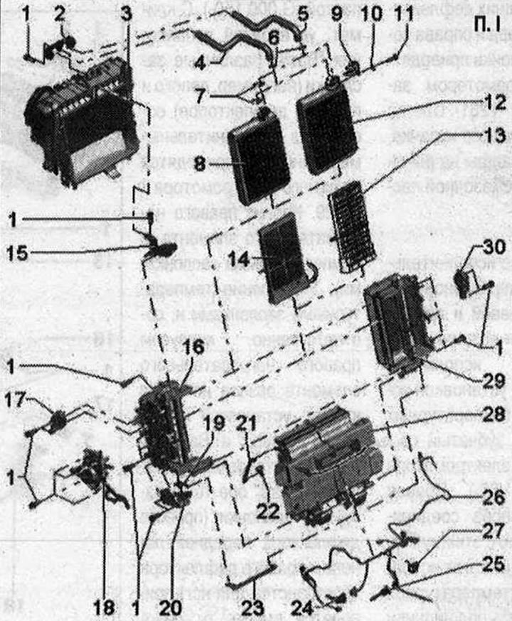
I 1. Screw; 2. Coolant pipe holder; 3. Evaporator body; 4. Coolant supply pipe. Coolant flow from the engine; 5. Coolant supply pipe. Coolant return flow to the engine; 6. O-ring. Replace. Lightly lubricate with coolant before installation; 7. Retainer: These clamps are installed at the factory and hold the coolant tubes in the factory heat exchanger; 8. Heat exchanger of the heating system. This version is installed by the manufacturer; 9. Fastening the coolant pipes in the replacement heat exchanger. Included in the scope of delivery of the replacement heat exchanger; 10. Washer. Included in the scope of delivery of the replacement heat exchanger; 11. Screw. Included in the scope of delivery of the replacement heat exchanger. Tightening torque 2.5 Nm; 12. Replacement heat exchanger of the heating system. This version is supplied as a spare part. Cover the heat exchanger with foam insulation according to the version of the climate control system and the car; 13. Cellular element. Provided for cars with a gasoline engine and for cars with a diesel engine, where the autonomous heater (additional equipment) controlled as add. Cover the cellular element with foam insulation according to the climate control version, installation 14. Heating element of the add. heater "Z35". Provided for vehicles with diesel (also for vehicles where the autonomous heater (additional equipment) controlled as add.). Cover the heating element of the additional heater "Z35" with foam insulation according to the design of the climate control system,; 15. Bracket; 16. Left heating element housing (with temperature dampers). The control of the temperature flaps and, accordingly, the left heating element housing is different for cars with climate control, the "Komfort" and "Basis" versions. With climate control, the "Basis" version installation, both temperature flaps (left front panel deflector and left footwell deflector) are driven together from a shaft. Different designs (with one or two bolt connections at the bottom). Lightly lubricate the cam disc guides, shaft bearings, gear elements and also the journals on the throttle levers (e.g. with solid lubricating paste "G 000150"); 17. Defrost flap servomotor "V107"; 18. Left mounting plate with actuator for footwell flap "V261". With cam disc, intermediate levers and connecting rods. Control of the air distribution flaps is different for the "Comfort" and "Basis" air conditioning systems. With air conditioning, "Basis" system, the flaps (front panel deflectors left and right and front footwell deflectors left and right)are connected via connecting rods in the air distributor housing. The flaps of the rear footwell vents on the left and right are connected by a shaft. All these flaps are driven by the footwell flap actuator motor "V261". Lightly lubricate the cam disc guides, shaft bearings and journals on the flap levers (e.g. with solid lubricating paste "G 000 150"; 19. Dentate segment; 20. Mounting plate with temperature flap actuator motor "V68". The left and right temperature flaps are controlled differently for the "Comfort" and "Basis" air conditioning systems. With the "Basis" air conditioning system, the shaft of the left temperature flaps is driven via a toothed segment from the temperature flap actuator motor "V68". The right temperature flap is also driven via a connecting rod that operates with this toothed segment from the temperature flap actuator motor "V68". Lightly lubricate the shaft bearings, toothed segments and journals on the flap levers (e.g. with solid lubricating paste "G 000 150"; 21. Defrost flap connecting rod; 22. Intermediate lever to the defrost flap actuator motor "V107"; 23. Temperature damper connecting rod. Depending on the production date, there are different connecting rods "A" (different design of the connecting element to the toothed segment and to the right temperature flap); 24. Footwell vent temperature sensor "G192". Installed in the left footwell vent; 25. Temperature sensor center, deflector "G191". Installed in the air duct to the central deflector of the front panel; 26. Wiring climate control, installation of the "Basis" version. Various versions. About; mean the position of the plugs before pulling them out, (similar plugs for different actuators and temperature sensors, can be accidentally mixed up). Secure the wiring harness to the mounting points provided on the body using clamps or fasteners so that it does not come into contact with moving parts; 27. Cable tie; 28. Climate air distributor housing. "Basis" execution settings. Do not disassemble the parts. Various versions on vehicles with climate control, installation in the "Komfort" and "Basis"versions. Lightly lubricate the disc cam guides, shaft bearings, gear elements, and trunnions on the flap levers (for example. Solid lubricating oil; paste "G 000150"). With the air conditioning system of the "Basis" version, various dampers (for example, left and right deflectors) connected by connecting rods and driven by one electric motor; 29. Right heating element housing (with temperature dampers). The control of the temperature flaps and, accordingly, the housing of the right heating element is different for cars with climate control, the "Komfort" and "Basis" versions. With climate control, the "Basis" version, both temperature flaps (right front panel deflector and right footwell deflector) are driven together from a shaft. Different designs (with one or two bolt connections at the bottom). Lightly lubricate the cam disc guides, shaft bearings, gear elements and also the journals on the throttle levers (e.g. with solid lubricating paste "G 000150"); 30. Execution. drive center, deflector "V102"
Material republished from the website: AudiManual.ru