
Table of contents: Connecting an independent heater to… ↓ Connecting an independent heater to… ↓ Removal and installation of the… ↓ Mounted parts of an independent… ↓ Autonomous heater bracket ↓ Connecting an independent heater to… ↓
Connecting an independent heater to a car without a check valve
"Arrows" indicate the coolant flow direction. When the coolant supply shut-off valve "N279" receives control signals (e.g., in autonomous heating mode). When the coolant is not warmed up and the ignition is off, the coolant is sucked in by the circulation pump "V55" directly from the air conditioning system heat exchanger.
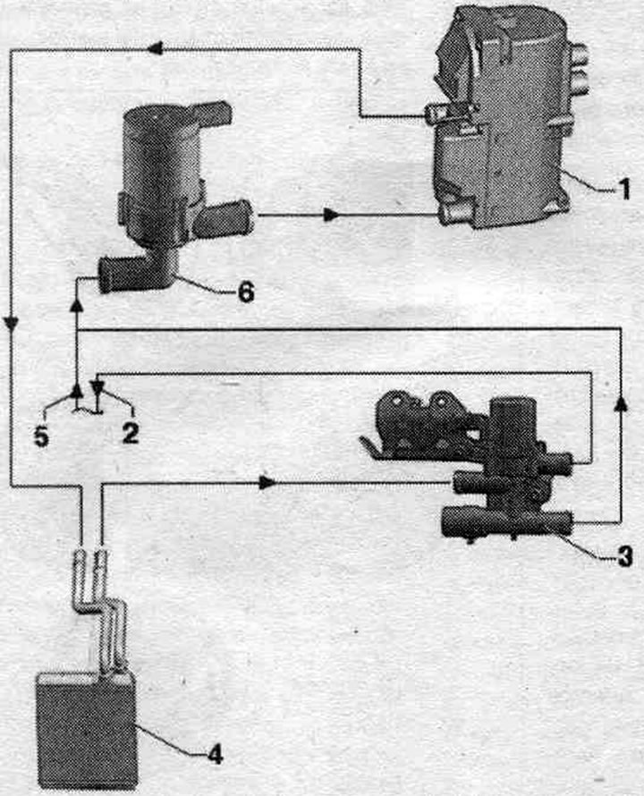
1. Autonomous heater.
2. Reverse flow of coolant to the engine.
3. Heater coolant supply shut-off valve "N279": controlled in the independent heater mode of the auxiliary heater "J364"; check the connection of the main lines; different designs, pay attention to the correct match.
4. Heat exchanger climate control installations.
5. Coolant flow from the engine.
6. Circulation pump "V55": the circulation pump "V55" is connected to the hose piping of the independent heater.
Connecting an independent heater to a car with a check valve
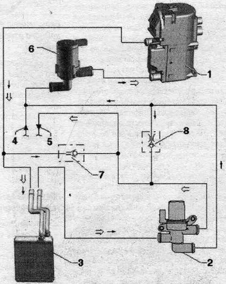
1. Autonomous heater.
2. Heater coolant supply shut-off valve "N279": in the autonomous heating mode, the used additional heater "J364" is controlled; check the connection of the main lines; different designs (on Audi A5 Coupe, Audi A4 and Audi 05), pay attention to the correct match.
3. Heat exchanger climate control installations.
4. Reverse flow of coolant to the engine.
5. Coolant flow from the engine.
6. Circulation pump "V55": the circulation pump "V55" is connected to the hose piping of the independent heater.
7. Check valve: a smaller diameter element for throttling the flow of liquid; installation location depending on the engine, in the water drainage box or motor. compartment.
8. Check valve: a smaller diameter element for throttling the flow of liquid; installation location depending on the engine, in the water drainage box or motor. compartment.
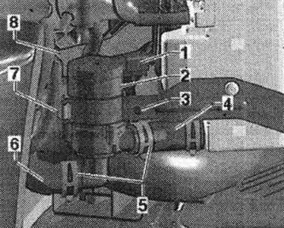
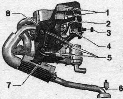
Removal and installation of the circulation pump "V55"
The cooling system is under pressure. Ignition is off. Relieve pressure in the coolant circuit by opening the expansion tank cap. system tank. cooling. Remove the front right wheel. Remove the front right fender liner. Clamp coolant hoses "6" and "8" (e.g. with clamps up to 25 mm in diameter "3094"). Loosen clamping clamps "5". Disconnect coolant hose "6" from circulation pump "V55" "2". Loosen screw "3" and remove clamp "7". Remove circulation pump "V55" "2" from coolant hose "4". Disconnect electrical connector "1" from circulation pump "V55" and remove the circulation pump.
Installation
Installation in reverse order. The new circulation pump - V55- with an empty coolant circuit can only be switched on after filling the coolant circuit, since running the new pump dry can lead to its failure. Since little coolant flows out during the above-described removal of the "V55" circulation pump, the liquid after removing the clamps from the hoses (add. remove the expansion tank cap) it enters the circulation pump - V55 - quickly, so there is no risk of damaging it. Connect the electrical connector to the V55 circulation pump only after removing the hose clamps (and filling the coolant circuit). Remove air from the coolant recirculation circuit.
Mounted parts of an independent heater
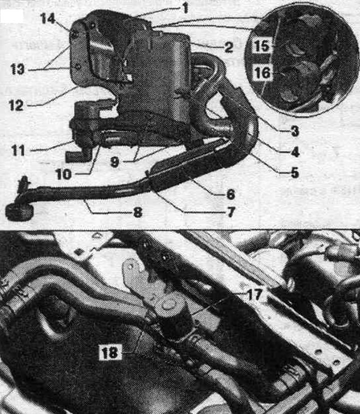
1. Holder.
2. Autonomous heater.
3. Clamp: bolt tightening torque 6 Nm; for corrugated tube to exhaust silencer.
4. Bolt: tightening torque 6 Nm; intake noise suppressor bracket; coated screw, replace.
5. Intake air noise muffler. Secure the suction hose with a clamp to prevent it from slipping off the air intake pipe of the independent heater. Additionally, secure the intake noise muffler with clamps on the independent heater bracket.
6. Exhaust muffler.
7. Clamp: tightening torque 6 Nm; for the exhaust pipe.
8. Exhaust pipe.
9. Bolt: tightening torque 6 Nm; to the bracket of the circulation pump "V55"; coated screw, replace; a rubber bushing is installed between the bolt and the bracket for separation.
10. Bolt: tightening torque 3.5 Nm; for clamping the circulation pump "V55".
11. Circulation pump "V55".
12. Fuel pipe. highways.
13. Nut: 2x; tightening torque 20 Nm; take into account the sequence, tightening.
14. Bolt: tightening torque 20 Nm; take into account the sequence, tightening.
15. Control wire plug connection: secured with a clamp on the bracket.
16. Power supply plug connection: secured with a clamp on the bracket: various plug connector designs depending on the version.
17. Heater coolant supply shut-off valve "N279": built into the water drainage box on the right; different designs (on Audi A5 Coupe, Audi A4 and Audi Q5), pay attention to the correct match.
18. Bolt: tightening torque 8 Nm; for the coolant shut-off valve of the heating system "N279".
Autonomous heater bracket
1. Plug connections for power supply and control wire.
2. Clamp with binder.
3. Nut, tightening torque 8 Nm.
4. Bolt, tightening torque 6 Nm.
5. Bolt, tightening torque 6 Nm (coated screw, replace).
6. Nut, tightening torque 6 Nm.
7. Bolt, tightening torque 6 Nm.
8. Heater bracket.
Connecting an independent heater to the vehicle's electrical system
Assignment of the 2-pin plug sockets (wire from the heating element to the "V55" circulation pump)
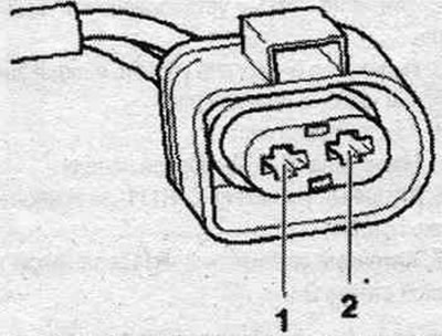
1. Control of the circulation pump "V55".
2. Connection to ground of the circulation pump "V55".
Assignment of 2-pin plug sockets (wire from the car side to the heating element)
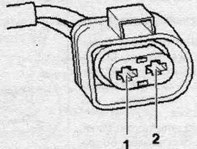
1. Power, contact 30.
2. Connection to ground.
6-pin plug connector socket assignment (wire from the car side to the heating element)
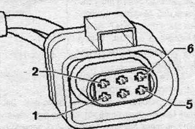
1. Data transmission line to the data bus (High-Speed-CAN-Bus).
2. Data transmission line to the data bus (Low-Speed-CAN-Bus).
3. Control of the shut-off valve for the heating system coolant "N279".
4. Control of the dosing pump "V54".
5. Currently not in use.
6. Data transmission line from the radio receiver of the independent heater "R64".
(The original article is available on the online resource AUDImanual.ru)