
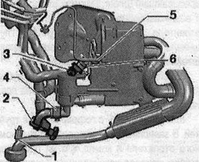
Remove nut -1-. Clamp the coolant hoses at position -2- (coolant supply to the autonomous heater) and -3- (coolant supply to the heat exchanger in the climate control unit), eg with hose clamps with a diameter of 25 mm -3094-. Loosen the clamps on the auxiliary heater coolant pipes -4- and -6- and remove the coolant hoses. Please note that coolant can only flow from the auxiliary heater, and the coolant circulation circuit of other components (engine, climate heat exchanger, installations) remains filled so that after installation the air only needs to be removed from the auxiliary heater. Loosen the clamp clamp -5-, disconnect and plug the fuel line. Unlock 6-pin connector -A- and 2-pin connector -B- (press it to the left side of the vehicle and, while pressing the connector, remove the lock) and remove.

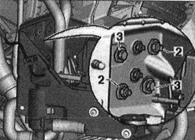
Depending on the vehicle version, both connectors are accessible through the hole for the removed fog lamp trim. From 10.2010, the gradual use of autonomous heaters with part number 4xx xxx xxx begins. This version of the auxiliary heater can be installed in a service center on a vehicle initially equipped with an auxiliary heater with part number 8R0 xxx xxx or 8K0 xxx xxx. Since the individual components differ for different versions of the autonomous heater (e.g. 2-pin plug connector for the power supply circuit of the additional control unit. heater -J364- -B-), when replacing individual components of the auxiliary heater, take into account the correct match. Unscrew the mounting nuts -2- and the mounting bolt -3-, and remove the auxiliary heater with the bracket; it is additionally secured to the side member with a second bolt -3-.
Autonomous heater attachments
Note. Please pay attention when replacing the correct version of the auxiliary heater (different versions for vehicles with petrol and diesel). Various car models are equipped with this auxiliary heater; when installed on a new car model, the part number of this auxiliary heater changes (for example, from 8K0 xxx xxx to 8R0 xxx xxx when the Audi Q5 model appeared and later to 4xx xxx xxx, etc.), so consider proper matching. Also take into account that an older version of the auxiliary heater cannot be installed in a vehicle equipped with a newer version of the auxiliary heater.
View"1"
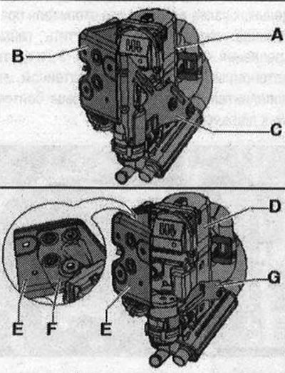
From model year 2009, be equipped with a modified auxiliary heater bracket; when replacing the auxiliary heater and bracket, ensure that the correct match is made. At the beginning of production, the auxiliary heater -A- was fixed to the bracket -B- and -C-. From model year 2009, the use of modified auxiliary heaters -D- was gradually introduced (improved acoustic performance, invisible from outside). These auxiliary heaters are mounted on a bracket -D- (using the additional element. hardness -E-) and -F-. If the auxiliary heater is mounted at the factory using brackets -B- and -C-. When replacing the auxiliary heater, it must be secured using brackets -D- (with additional element hardness -E-) and -F-.
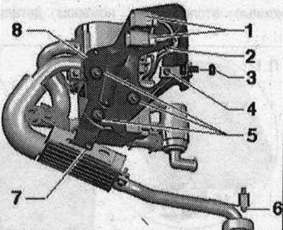
The following figure shows an auxiliary heater with a bracket "2", installed at the start of production in 2009 mod. year. All nodes that did not work can be seen in the view "2".
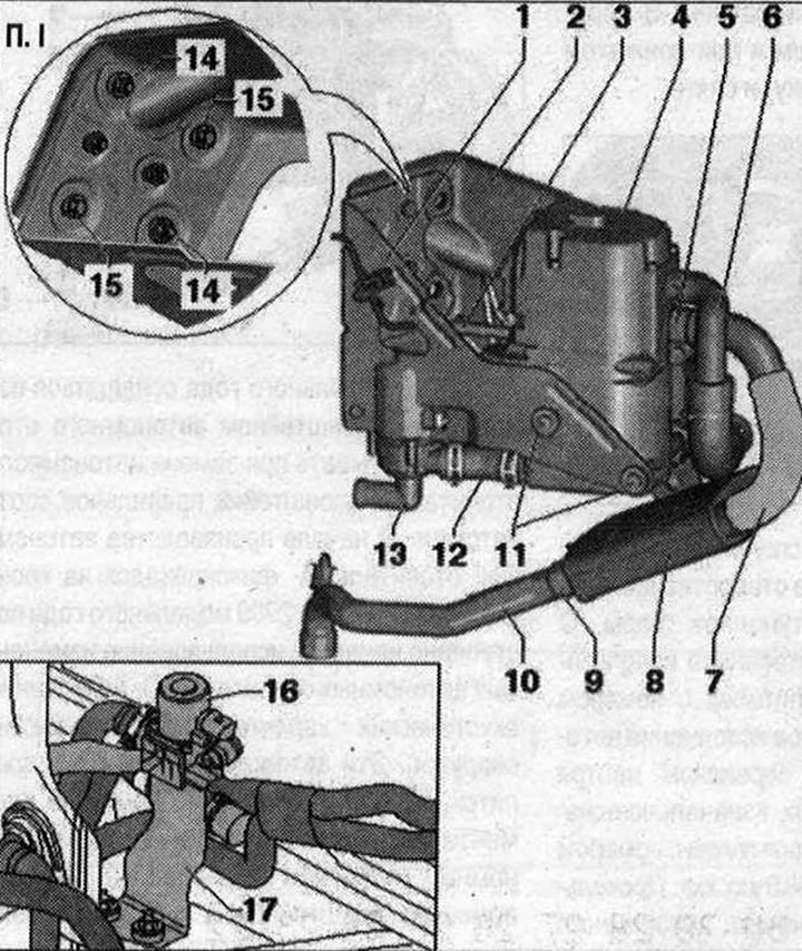
I 1. Bracket 1. Bracket "1" and bracket "2" screwed together. They have different designs depending on the production period; 2. Bracket "2"; 3. Fuel pipe highways; 4. Autonomous heater. Various versions, auxiliary heaters with part number 8K0.xxx.xxx cannot be installed. in addition, various designs are available depending on the production period and type of fuel (Certain functions are configured differently for petrol and diesel engines); 5. Clamp. Bolt tightening torque 6 Nm. For corrugated pipe to exhaust silencer; 6. Intake air noise suppressor. Attached with holders and cable ties to the bracket "2". Secure the suction hose with a clamp to prevent it from sliding off the air intake pipe of the autonomous heater. Additionally, secure the intake noise muffler with clamps on the auxiliary heater bracket; 7. Thermal insulation of the corrugated tube to the exhaust silencer (not available on all versions); 8. Exhaust muffler with corrugated pipe. Depending on the version of the autonomous heater and the set. the vehicle has thermal insulation installed on the exhaust pipe, which is installed between the auxiliary heater and the exhaust silencer (to protect surrounding parts); 9. Clamp for the exhaust pipe. Tightening torque 6 Nm; 10. Exhaust pipe. The exhaust gas must exit the exhaust pipe unhindered. After performing work on the auxiliary/auxiliary heater or on the muffler, it is necessary to check the neck of the exhaust pipe: when passing through the muffler module, it must be located at right angles to the muffler module; 11. Bolt for bracket "1". Tightening torque 6 Nm. Coated self-tapping screw, replace. A rubber bushing is installed between the bolt and the bracket for disconnection; 12. Coolant hose between circulation pump -V55- and auxiliary heater; 13. Circulation pump -V55-; 14. Nut, 2x. Tightening torque 20 Nm. Pay attention to the tightening sequence; 15. Bolt, 2x. Tightening torque 20 Nm. Pay attention to the tightening sequence; 16. Heater coolant shut-off valve -N279-. Built into the drainage box on the right. Control signals to -N279- are only permitted at a certain engine speed (at the moment no higher than 1200 rpm.), therefore, take into account the correct design, coding and adaptation of the auxiliary heater; 17. Holder for heating coolant shut-off valve -N279-. Tightening torques for bolts and nuts (for attaching heater coolant shut-off valve -N279- to holder and bracket in vehicle), respectively, 8 Nm.
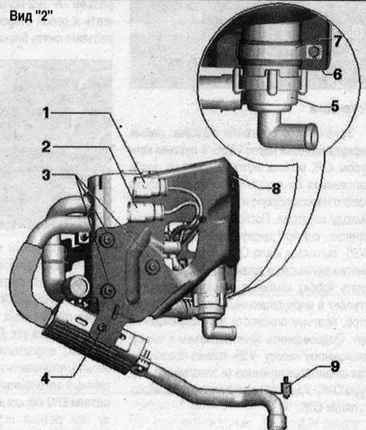
View "2" 1. Plug connection for control wire. Fixed with a clamp on the bracket "2"; 2. Plug connection for power supply. Fixed with a clamp on the bracket "2"; 3. Bolt for circulation pump bracket -V55-. Tightening torque 6 Nm. Coated self-tapping screw, replace. A rubber bushing is installed between the bolt and the bracket for disconnection; 4. Exhaust muffler bolt. Tightening torque 6 Nm 5. Circulation pump -V55-; 6. Bolt for clamping circulation pump -V55-. Tightening torque 3.5 Nm; 7. Clamp for circulation pump -V55-; 8. Bracket "2". bracket "G and bracket "2" screwed together; 9. Rubber-metal support.
Autonomous heater bracket
This picture shows the auxiliary heater bracket installed at the beginning of production in 2009 mod. year. Differs from the bracket, the installation of which has gradually begun since the change in 2009 mod. year.
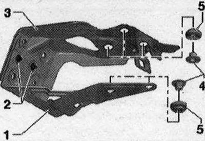
1. Bracket "1"; 2. Nut, tightening torque 8 Nm; 3. Bracket "2"; 4. Axle box; 5. Bushing.
Checking the heater glow plug -Q9-
Carry out work to prepare for testing the autonomous heater parts. Disconnect connector -2- from the auxiliary heater.
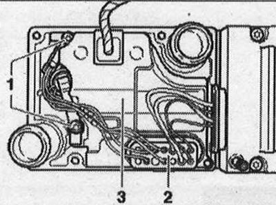
Measure the resistance at the connector between the contact "3" and the heater housing.
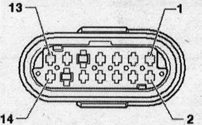
Specified value: Q. Measure the resistance at the connector between the contacts "3" and ''6". Set value: less than 1 Q. Nominal value: 0.42 - 0.63 0~ (at 20 + / -2°С).
Note. It is impossible to measure resistances less than 1 Q with sufficient accuracy using conventional measuring instruments, so this test can only determine significant damage to the component. When a voltage of 9 V is applied to the glow plug of the heater 09, the current consumption should be 9-20 A.
Visitor comments