
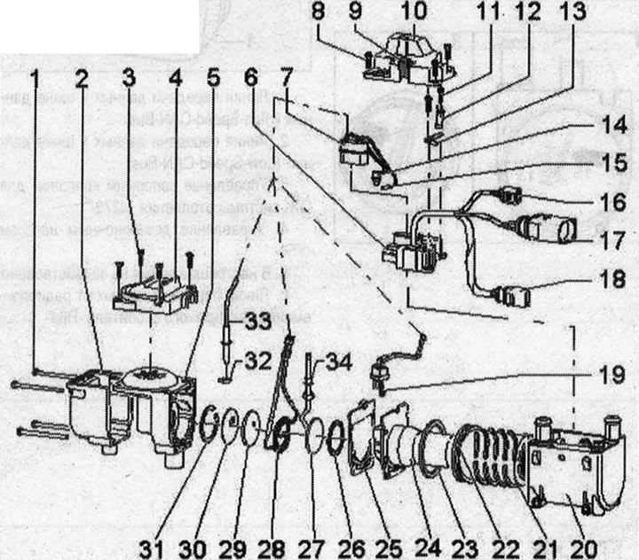
1. Bolt M5x80.4x. Tightening torque 6 Nm; 2/4. Heater combustion air fan housing -V6-; 3. Bolt M4x16.4x. Tightening torque 3 Nm; 5. Heater combustion chamber fan -V6-. Replace. Do not disassemble into parts; 6. Used add. heater -J364-. Coolant output when the pressure in the coolant circuit increases with an incorrectly installed or unsuitable clamp. If the clamp -G18- or -G587- is not installed correctly, it may spring out of the mountings. Attention should be paid to the correct distribution and installation of clamps; 7. Connector, 14-pin. to the auxiliary heater control unit. Socket layout and wire color: Temperature sensor -G18-: socket 10 - black wire, socket 11 - black wire; Flame sensor -G64-: socket 1 - brown wire; socket 2 - brown wire; Temperature sensor 2 additional and auxiliary heater -G587-: socket 7 - white wire, socket 8 - white wire. Heater glow plug -Q9-: socket 3 - brown wire, socket 6 - white wire; Combustion air fan -V6-: socket 13 - black wire; socket 14 - brown wire; Heating element for fuel preheating system -Z66-: socket 9 - black wire, socket 12 - black wire; 8. Bolt M4x 16.4x. Tightening torque 3 Nm; 9. Clip for laying the wire; 10. Additional control unit casing. heater -J364-; 11. Bolt M4x12. Tightening torque 3 Nm; 12. Clamp for temperature sensor -G18-. Clamp for temperature sensor and temperature sensor 2 for add. and autonomous heaters -D587- exist in various designs. In -J364- with part number 8xx xxx xxx, clamps can only be installed without spacer ring. For -J364- with part number 4xx xxx xxx only clamps with a spacer ring can be installed. Therefore, you should pay attention to the correct distribution (Part number for clamps and additional control unit. heater -J364- must match); 13. Clamp for temperature sensor 2 extra. and auxiliary heater -G587-; 14. Temperature sensor -G18-; 15. Temperature sensor 2 extra. and auxiliary heater -G587-; 16. 2-pin connector to circulation pump -V55-; 17. 6-pin plug connector to the additional control unit. heater -J364-; 18. 2-pin plug connector for power supply. Available in different designs 19. Heater glow plug -Q9-. Nominal voltage: 8 V. If necessary, carefully clean the heating pin using a brass wire brush (spark plug brush). There are different versions of the heater glow plug -Q9-, so ensure correct matching; 20. Heat exchanger housing. Clean inside and outside with a brass brush (spark plug brush); 21. Heat exchanger. Observe installation position. Clean inside and outside with a brass brush (spark plug brush); 22. Seal O-ring. Replace. When installing, lightly moisten the coolant; 23. Seal. Replace; 24. Burner cartridge. Clean inside and outside with a brass brush (spark plug brush). Various versions (for petrol and diesel engines); 25. Shaped gasket. Replace; 26. Seal. Replace; 27. Fuel evaporator. Various versions (for petrol and diesel engines); 28. Heating element for fuel preheating system -Z66-; 29. Seal. Replace; 30. Disc; 31. Retaining ring; 32. Graphite seal. Replace. Observe the installation position; 33. Flame sensor -G64-; 34. Clip. Available only in gasoline-powered heaters (put on fuel fuel pipe evaporator)
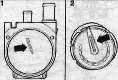
Installation position of the heat exchanger
Connecting the auxiliary heater to the electric vehicle system
Purpose of the 2-pin plug sockets (cable from heating element to circulation pump -V55-)
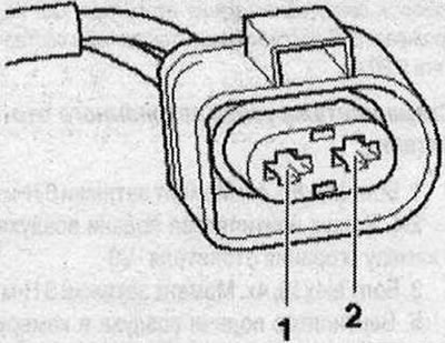
1. Circulation pump control -V55-; 2. Ground connection for circulation pump -V55-
Purpose of the 2-pin plug sockets (wire from vehicle side to heating element)
- 1. Power, pin 30.
- 2. Ground connection
Purpose of the 6-pin plug connector sockets (wire from vehicle side to heating element)
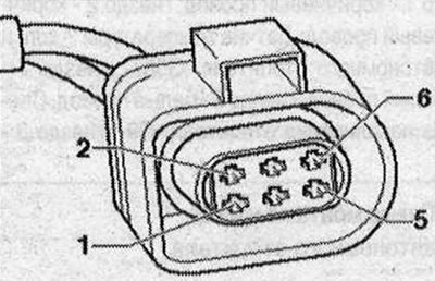
1. Data line to data bus (High-Speed-CAN-Bus); 2. Data line to data bus (Low-Speed-CAN-Bus); 3. Control of the heating coolant shut-off valve -N279-; 4. Control of dosing pump -V54-; 5. Currently not in use; 6. Data line from auxiliary heater radio -R64-.
Visitor comments