Repair Chevrolet Repair Toyota Repair Honda Repair AvtoVAZ Repair Mercedes-Benz Repair BMW Repair Opel
Home  |  Contacts  |  Sitemap  |    
English Русский
Български
Беларускі
Український
Српски
Hrvatski
Română
Polski
Slovenský
Magyar
AudiManual.ru


  • AUDI 80
  • AUDI 100
  • AUDI A3
  • AUDI A4
  • AUDI A6
  • AUDI A8
  • AUDI Q
  • OTHER
  • ARTICLES
C4 (1990-1994) C4 (1990-1994, petrol) C3 (1982-1990) C3 (1982-1990, petrol) C3 (1982-1990, diesel)

Hydraulic tappets — operating principle (Audi 100 C3)

  • Home
  • Audi 100
  • C3 (1982-1990, petrol)
  • 5 cylinder engine
  • Engine repair
  • Hydraulic tappets — operating principle
            0
Table of contents: Design ↓ Operating principle ↓
Sectional view of hydraulic valve lifter: 1 - camshaft cam; 2 - accumulation chamber; 3 - check…

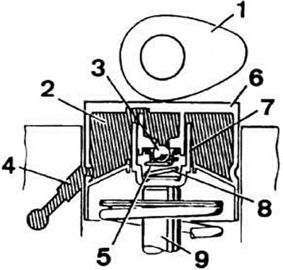
Sectional view of hydraulic valve lifter: 1 - camshaft cam; 2 - accumulation chamber; 3 - check valve; 4 - oil supply channel to the pusher; 5 - high pressure chamber; 6 - pusher; 7 - cylinder; 8 - valve clearance compensation spring; 9 - valve stem


Design


The hydraulic pusher consists of two main moving parts: the pusher itself 6 (see picture), serving simultaneously in the process of work of the plunger, and the cylinder 7.

Under the pressure of spring 8, the plunger and cylinder move away from each other, due to which the gap between the camshaft cam and the end of the valve stem is selected.

Filling and locking of the high-pressure chamber 5 is ensured by the check valve 3.

Operating principle


Valve lift start moment


At the moment the camshaft cam hits the valve stem, the check valve supports the chamber and the pressure in it increases. The increase in pressure does not lead to compression of the volume occupied by oil in the high-pressure chamber. The tappet thus works as a solid body.

Valve lift moment


The camshaft cam presses the tappet with force, which leads to a significant increase in pressure in the tappet cavity. A small amount of oil is ejected through the gaps between the cylinder and the plunger, which leads to compression of the hydraulic tappet by a maximum of C. 10 mm. Such compression is structurally necessary for running in the tappets even with a decrease in the distance between the camshaft cam and the tappet end.


Valve clearance compensation


The camshaft cam does not press on the tappet, and the pressure in the high-pressure chamber drops. The spring separates the plunger and the cylinder, thereby compensating for the gap between the cam and the end of the valve stem.

At this point, the check valve opens, and some amount of oil enters the high-pressure chamber. This amount corresponds directly to the gap being compensated.

Note. The valve train noise after the engine is started is normal. This is due to the fact that when the engine is stopped, some of the oil flows out of the tappet cavity. When the engine starts, the high-pressure chamber is filled again and the noise stops. Filling of the high-pressure chamber continues until the engine warms up to operating temperature.


The design of the cylinder head lubrication circuit eliminates the complete removal of oil from the channels after the engine is stopped. This ensures that oil is supplied to the tappets immediately after the engine is started and that noise in the valve mechanism drive ceases as quickly as possible.

Operation of hydraulic tappets at the moment of engine start


After the engine is stopped, oil flows out of the channels coming from the oil pump, and the channels supplying oil to the tappets remain filled with oil. To prevent air from entering the tappet cavity under the action of oil pressure when the engine is started, there are ventilation holes in the channels supplying oil to the tappets, which provide automatic purging of the tappet cavity. In addition, the ventilation hole allows reducing the pressure of the oil entering the tappets.
The article was checked by auto expert Maxim Rybakov
This article is available at russian, bulgarian, belarusian, ukrainian, serbian, croatian, romanian, polish, slovak, hungarian

Share information:
Previous articles
Audi 100 C3: Engine repair
Next articles

Checking and adjusting clearances in the valve drive mechanism
Tightening torques for main threaded connections
Valve timing mechanism — technical characteristics
Crank mechanism — technical characteristics
Checking the technical condition of hydraulic tappets
Timing mechanism parts
Removal and installation the camshaft drive belt
Checking and adjusting the tension of the camshaft drive belt


Similar articles on other Audi car models:
Operating principle of hydraulic tappets Audi 80 B2 (1979-1986)
Bleeding air from the clutch hydraulic system Audi A3 Type 8L (1996-2003)
Hydraulic tappets Audi A4 B5 (1994-2001, petrol)
Hydraulic tappets Audi A6 C4 (1994-1997)
Checking hydraulic valve lifters Audi A8 D2 (1994-2002)
Hydraulic clutch system Audi Q5 Type 8R (2008-2017)
Checking hydraulic tappets Audi A2 (1999-2005)
Link to this page in different formats


Visitor comments

No comments yet


How much will 33 + 47 =


100(C4, 1990-1994) 
  • General information
  • User manual
  • Power unit
  • Engine repair
  • Ignition system
  • Fuel system (gasoline)
  • Fuel system (diesel)
  • Lubrication system
  • Cooling system
  • Exhaust system
  • Transmission
  • Clutch
  • Car gearbox
  • Drive shafts
  • Chassis
  • Car suspension
  • Steering
  • Wheels and tires
  • Brake system
  • Body
  • Ventilation and heating
  • Body repair
  • Electrical equipment
  • Power devices
  • Lighting and appliances
  • Electrical circuits
 
100(C4, 1990-1994, petrol) 
  • General information
  • Operation and maintenance
  • Power unit
  • Engine repair
  • Exhaust system
  • Cooling system
  • Supply system
  • Air filter
  • Mono-Motronic injection system
  • Digifant injection system
  • KE-III-Jetronic and KE-Motronic
  • MPI and MPFI injection system
  • Transmission
  • Clutch
  • Car gearbox
  • Chassis
  • Suspension and steering
  • Brake system
  • Wheels and tires
  • Body
  • Exterior
  • Interior
  • Electrical equipment
  • Fuses and relays
  • Power devices
  • Ignition system
  • Lighting and signaling
  • Equipment and devices
  • Electrical circuits
 
100(C3, 1982-1990) 
  • General information
  • User manual
  • Maintenance
  • Specifications
  • Power unit
  • Engines 4-cylinder
  • Engines 5-cylinder
  • Diesel engine
  • Cooling system
  • Power system (carburetor)
  • Power system (injector)
  • Fuel system (diesel)
  • Transistor ignition system
  • Electronic ignition system
  • Transmission
  • Clutch
  • 4 speed gearbox 014
  • 5 speed gearbox 013 and 093
  • 5 speed gearbox 016 and 012
  • Shift mechanism KP 016
  • Automatic transmission
  • Front wheel drive
  • Chassis
  • Front suspension
  • Rear suspension
  • Steering
  • Brake system
  • Body
  • Body elements
  • Electrical equipment
  • Lighting and appliances
  • Power devices
  • Electrical circuits
 
100(C3, 1982-1990, petrol) 
  • General information
  • Maintenance and operation
  • 4 cylinder engine
  • Engine repair
  • Cooling and lubrication system
  • Supply system
  • Ignition system
  • 5 cylinder engine
  • Engine repair
  • Cooling and lubrication system
  • Supply system
  • Ignition system
  • Transmission
  • Clutch and drive shafts
  • 4 speed gearbox 014
  • 5 speed gearbox 013 and 093
  • 5 speed gearbox 016 and 012
  • Automatic gearbox
  • Chassis
  • Steering
  • Front suspension
  • Rear suspension
  • Brake system
  • Body
  • Body elements
  • Doors, locks and windows
  • Body repair
  • Electrical equipment
  • Equipment and devices
  • Power devices
  • Electrical circuits
 
100(C3, 1982-1990, diesel) 
  • General information
  • User manual
  • Maintenance
  • Troubleshooting
  • Power unit
  • Engine in a car
  • Engine removed
  • Cooling system
  • Fuel system
  • Exhaust system
  • Starting and charging
  • Preheating
  • Transmission
  • Clutch
  • Mechanical gearbox
  • Automatic gearbox
  • Drive shafts
  • Chassis
  • Brake system
  • Suspension
  • Steering
  • Body
  • Exterior
  • Interior
  • Electrical equipment
  • Equipment and devices
  • Electrical circuits
 
AudiManual.ru © 2017-2026 · Mobile version · Feedback · Sitemap: EN BG BY UA RS HR RO PL SK HU · Site search · News and articles
80 B2 · 80 B3 petrol · 80 B3 · 80 B4 · 100 C3 diesel · 100 C3 petrol · 100 C3 · 100 C4 petrol · 100 C4 · A3 Type 8L · A4 B5 petrol · A4 B5 · A4 B6 petrol · A4 B6 · A4 B7 · A4 B8 · A6 C4 · A6 C5 · A6 C5 Allroad · A8 D2 · Q5 Type 8R · Q7 Typ 4L · Audi A2 ·
This site uses cookies 🍪. Click the button to accept this fact.