
Table of contents: Model engines "WH", "WC", "KP", "RT" ↓ Engines of the models "KU" and "NF" ↓
Model engines "WH", "WC", "KP", "RT"
Examination
Warm up the engine to operating temperature (coolant temperature above +35°C, cylinder head warm).
Disconnect the throttle cable.
Disconnect the crankcase ventilation hose.
On fuel-injected engines, disconnect the pressure regulator plug and disconnect the vacuum supply hose from it. Remove the pressure regulator mounting bolts and move the upper hoses away from the cylinder head cover.
Remove the cylinder head cover.
Turn the crankshaft, bringing each cam sequentially with its back to the end of the pusher.
Using a set of feeler gauges, measure the gaps between the back of the cam and the adjusting washer on the tappet sequentially for all valves.
Warning: It is not recommended to turn the camshaft directly by the pulley mounting bolt, as too much force may cause the valve timing to be out of adjustment.
Clearances in the valve drive mechanism
The clearance between the camshaft cams and the adjusting washers on a warm engine should be 0.25±0.05 mm for intake valves and 0.45±0.05 mm for exhaust valves; on a cold engine, respectively 0.20+0.05 and 0.40±0.05 mm.
Adjustment
Perform the first valve clearance adjustment after disassembling the mechanism on a cold engine. Adjust the clearances if you find deviations from the permissible values during the check.
Record the clearance values Z for each valve.
Turn the crankshaft sequentially, taking into account the order of operation of the cylinders, installing the protruding part of the cam on the tappet of one of the valves and measuring the clearance of the valves of the opposite cylinder, the tappets of which are unloaded.
Using tool 2078, press the tappets into the cylinder head body. Rotate the tappet slot perpendicular to the camshaft axis and install a puller to extract the adjusting washers.
Remove the adjusting washer using a 10-208 puller or a thin-bladed screwdriver.
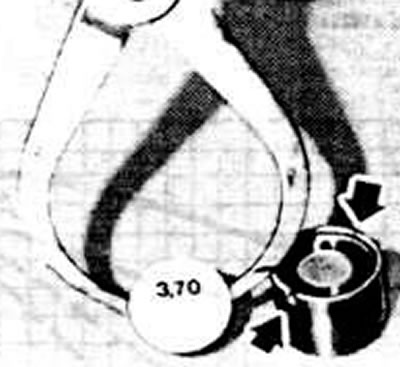
Removing the adjusting washer with a puller. Install the new adjusting washer with the marked side facing the valve stem. The arrows show the cutouts for installing the puller jaws
Measure the thickness T of the removed washer with a micrometer and calculate the thickness of the new washer using the formula:
Tn=T+Zi-Zn,
where
Tn - thickness of the new washer;
T — thickness of the removed washer;
Zi - measured gap;
Zn — nominal clearance.
Select an adjusting washer of the required thickness and install it on the pusher with the mark facing the pusher.
Remove tool 2078.
Adjust the clearances for the remaining valves in the same manner.
Make final adjustments to the clearances on a warm engine if the initial adjustment was made on a cold engine.
Engines of the models "KU" and "NF"
The valve drive mechanism of the KU and NF engine models uses hydraulic tappets, which provide automatic compensation of valve clearances.
The original material is located on the website: AUDImanual.ru