
Crankshaft
The crankshaft is steel, forged. The shaft has six bearings. There are lubrication grooves in the upper shells of the main bearings. There are ten counterweights on the cheeks of the shaft, forged together with the shaft.
Crankshaft main journal diameters, mm:
- nominal: 58.00-0,022-0,042
- 1st repair: 57.75-0,022-0,042
- 2nd repair: 57.50-0,022-0,042
- 3rd repair: 57.25-0,022-0,042
Diameter of crankshaft connecting rod journals, mm:
- nominal: 46.00-0,022-0,042
- 1st repair: 45.75-0,022-0,042
- 2nd repair: 45.50-0,022-0,042
- 3rd repair - 45.25-0,022-0,042
Crankshaft axial clearance, mm:
- nominal: 0.07-0.18;
- maximum: 0.25.
Clearance between liners and crankshaft journals, mm:
- nominal: 0.016-0.075;
- maximum permissible in operation: 0.16.
Pistons
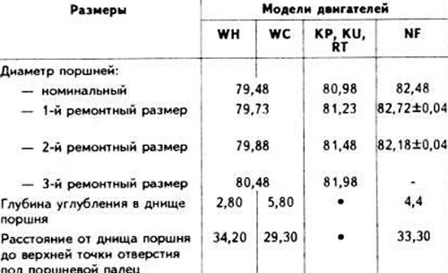
The pistons are made of aluminum alloy with steel inserts. Each piston has two compression rings and one oil scraper ring. For correct installation of the piston in the cylinder, there is an arrow on the bottom, which should face the 8 side of the camshaft drive. Measure the piston diameter at a distance of 10 mm from the edge of the piston skirt at an angle of 90° relative to the axis of the piston pin. The deviation of the piston diameter from the nominal size should not exceed 0.04 mm.
Main dimensions of pistons
Piston pins
The piston pin is floating. It is held from axial movement by two retaining rings.
Piston pin length, mm: 54.
Since July 1985, the piston pin length has been increased from 54 to 57 mm. The grooves for the retaining rings in the piston pin holes have been shifted accordingly. When repairing, only pistons and pins of the same configuration should be installed.
Piston rings
Each piston is fitted with three rings: two compression rings and one oil scraper ring.
Piston ring gap, mm:
- nominal: 0.25-0.50;
- maximum permissible: 1.00.
Clearance between piston ring and groove, mm:
- nominal: 0.02-0.08;
- maximum permissible: 0.10.
Connecting rods
Connecting rods are steel, forged, with an I-section rod, with thin-walled liners. A bushing is pressed into the upper head of the connecting rod.
There are technological lugs on the lower head and on the connecting rod cover, showing how to install them correctly. The lugs should be directed towards the 8 side of the camshaft drive.
Clearance between liners and crankshaft journals, mm:
- nominal: 0.015-0.062;
- maximum permissible in operation: 0.12.
Maximum axial clearance of the connecting rod on the crankshaft journal, mm: 0.4.
Distance between axes of connecting rod head holes (engine model "NF"), mm: 144.