
Table of contents: Disconnecting and connecting the… ↓ Connection ↓
Take into account the instructions for removing and installing the clutch master and slave cylinder.
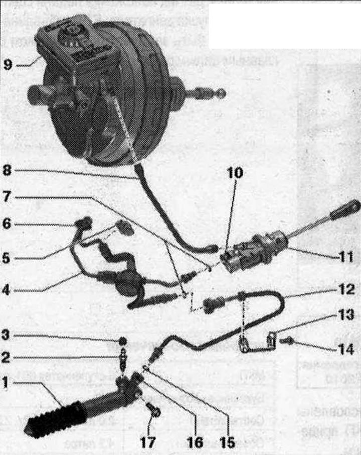
Hydraulic clutch system 1. Clutch slave cylinder: Do not operate after removing the clutch pedal; after working on the hydraulic clutch drive, bleed the clutch drive; brake fluid must not be allowed to get on the gearbox; 2. Air vent screw: 5.5 Nm; follow the order of actions when pumping; a broken bleed nipple can be unscrewed with a key with an internal Allen key (3 mm); 3. Protective cap; 4. Pipe-hose line: with frequency modulator; nipple connectors on the master and slave cylinders; 5. Retaining clamp; 6. Nozzle; 7. O-ring seal: replace if damaged; install, moistening with brake fluid; 8. Clutch master cylinder feed hose: with integrated sealing nozzles; if the sealing nozzles are damaged, replace the supply hose; 9. Brake fluid reservoir; 10. Locking clamp: to remove and install the pipe-hose line, pull it out until it stops; 11. Clutch master cylinder: after working on the hydraulic clutch drive, bleed the clutch drive; 12. Pipeline; 13. Bracket: for pipeline; is attached to the gearbox; 14. Bolt: 20 Nm; 15. Sealing ring: replace if damaged; install, moistening with brake fluid; 16. Locking clamp: to remove and install the pipe-hose line, pull it out until it stops; 17. Bolt: 20 Nm
Disconnecting and connecting the pipe and hose line
Unlock the locking bracket "A" with a screwdriver and pull it out until it stops. Disconnect the pipe-hose line.
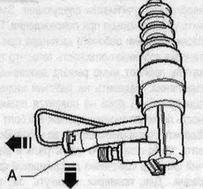
Connection
Replace the sealing ring if damaged. Press the locking clip "A" until it stops. Insert the pipe-hose line into the nipple until it locks into place. Pull the pipe-hose line to check.