



Hydraulic clutch system
Follow the instructions for removing and installing the clutch master and slave cylinders.
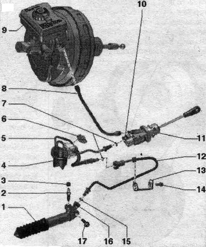
1. Clutch slave cylinder: After removing, do not press the clutch pedal; after working on the hydraulic clutch drive, bleed the clutch drive; brake impact. liquids on the gearbox are not allowed.
2. Bleed nipple: 5.5 Nm; follow the procedure when pumping; a broken bleed nipple can be unscrewed with an internal hex key (3 mm).
3. Cap.
4. Nozzle.
5. Pipe and hose line for nipple connectors on the master and slave cylinders; with a frequency modulator.
6. Mounting clip.
7. Sealing ring: replace if damaged; install by wetting the brake. liquid.
8. Feed hose for main cyl. clutch; with built-in seals. nozzles; in case of damaged seals. replace the feed hose on the nozzles.
9. Brake reservoir. liquids.
10. Locking clamp: To remove the hose line, pull it out as far as it will go.
11. Clutch master cylinder: after working on the hydraulic clutch drive, bleed the clutch drive.
12. Pipeline: for nipple connectors of the tubular-hose line and the working cyl. clutch.
13. Pipeline holder: attached to the control panel.
14. Bolt: 20 Nm.
15. Sealing ring: replace if damaged; install by wetting the brake. liquid.
16. Locking clamp: To remove the hose line, pull it out as far as it will go.
17. Bolt: 20 Nm; working cyl. clutch to the gearbox.
Bolt tightening sequence - clutch module to driven disc
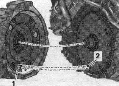
Use only new screws. Tighten the bolts with a 16 mm ring spanner "VAG 1332/14". The next step is only necessary if the driven disc is installed with locking pin "2." If the locking pins of driven disc "2" do not engage the holes in clutch module "1," this can cause serious problems with clutch operation. Additionally, align the position of the driven disk in relation to the clutch module so that the locking pins "2" (if available) on the driven disk could enter the large holes "1" on the clutch module.
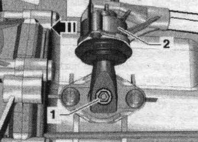
Engage 6th gear by removing shift shaft "1" and shifting gear lever "2" forward in the "direction of the arrow".
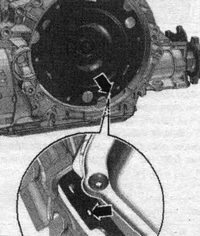
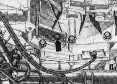
The next stage of work is absolutely necessary to ensure uniform contact with the driven disk without distortion. Rotate both fronts. wheels in one direction so that the clutch module makes 1 full revolution. The inspection hole "arrow" should be visible again in the recess of the gearbox housing.
Screw in the first bolt "arrow" (2 Nm) all the way. Turn the clutch module by both front. wheels 180° in the direction of engine rotation. Now screw in the 2nd bolt and tighten to the specified torque. Now screw in the remaining bolts one by one and tighten them immediately (even a bolt that has just been screwed in) moment.
Clutch repair
Instructions: To work on the clutch, the transmission must be removed. To avoid damaging the SAC pressure plate, follow the instructions for working with the SAC pressure plate during removal and installation. With the SAC pressure plate (self-adjusting clutch pressure plate) when replacing only the clutch disc, it is necessary to return the adjusting ring to its original position. Replace the clutch disc/pressure plate with damaged or loose rivets. Select the clutch disc and pressure plate according to the engine letter designation. The pressure plates are protected against corrosion and lubricated with grease. Do not clean the pressure plate, except for the friction surface of the clutch disc. Otherwise, the clutch life will be significantly reduced. The friction surface of the pressure plate and dual mass flywheel must be thoroughly cleaned (degrease). To reduce the smell of burnt clutch, thoroughly clean the gearbox housing in the clutch area and the engine on the gearbox side. If there is visible damage to the drive shaft surface in the area of the needle bearing of the dual-mass flywheel "arrow", the drive shaft and the needle bearing of the dual-mass flywheel must be replaced. Replace the drive shaft.
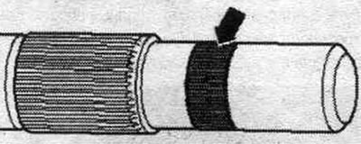
Check the primary shaft at the installation location in the driven disk "arrow" for signs of running-in. If necessary, replace the driven disk needle bearing. Clean the gear connection first. shaft and, when using a clutch disc, the hub gear connection, remove any corrosion and apply a very thin layer of clutch disc gear grease -G 000 100- to the gear connection. Then move the clutch disc back and forth until the hub moves easily on the shaft. Be sure to remove excess grease. Remove grease from the drive shaft journals down to the splines.
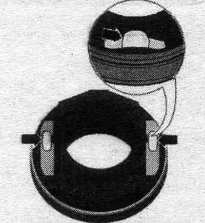
Lack of lubrication in the places where the clutch release bearing is attached can cause a crackling sound when the clutch is engaged. Apply a sufficient amount of solid lubricant -G 000 150- to the bearings of the clutch release bearing "arrows".
Do not install the clutch module on the transfer plate "arrow" on one side only. This can cause the transfer plate to become warped, leading to operational problems.
Removal and installation the clutch module
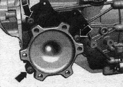
Remove the gearbox and secure it with tension belt "1" to the gearbox mount "T40173." To prevent oil leakage after removing the left shaft with flange, tilt the gearbox slightly backward. Loosen the bolts "arrow" of the left shaft with flange support.
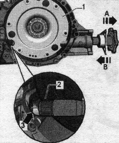
Pull the shaft with flange out of the gearbox in the "direction of arrow A". In doing so, hold the shaft end "2" centered in the hole in the front final drive "arrow 3". If the shaft is not held centered during subsequent removal, the shaft gear ring "2" will hit the shaft seal "arrow 3" between the differential and the gearbox housing. Damaged seal. replace the shaft seal.
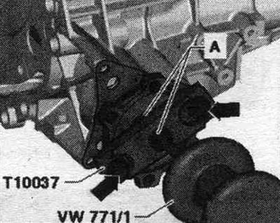
If the left axle shaft with flange cannot be removed by hand, carefully remove the axle shaft with flange using a mounting tool. tool "VW 771". To do this, secure the plate of the removable device "T10037" on the axle shaft with the "arrow" flange and connect it to the spindle mounting. tool "VW 771" (nuts "A").
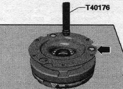
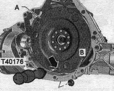
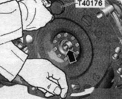
Secure the puller "T40176" to the clutch module "A" with the nut "B" "arrow".
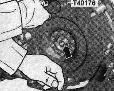
Rotate the T40176 puller upward. To prevent the clutch module from tipping over, hold the bottom of the clutch module as shown in the figure. When removing and installing the clutch module, ensure that the shaft seals and needle bearing in the dual mass flywheel "arrow" are not damaged. Damaged radial shaft seals and needle bearings must be replaced. Remove the clutch module without tilting it from the drive shaft "arrow".
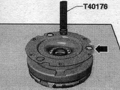
Do not install the clutch module on the transfer plate "arrow" on one side only. This can cause the transfer plate to become warped, leading to operational problems. Carefully place the clutch module with the pressure plate facing downwards on the workbench.
Installation
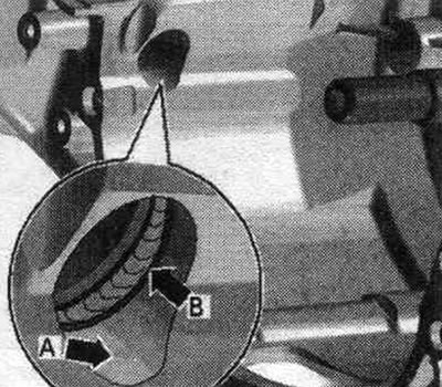
Installation in reverse order. Lubricate the clutch release bearing as specified. Thoroughly clean the left half-shaft with flange, the gearbox housing in the differential access area "arrow A" and the shaft sealing ring "arrow B". If the shaft sealing ring between the differential and the gearbox housing "arrow B" is damaged, replace it. Fill the space between the working edge and the boot "arrow B" halfway with consistent grease -G 052 128 A1-.
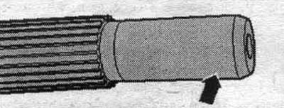
Clean the drive shaft "arrow". Lubricate the drive shaft splines with a thin layer of clutch disc spline grease -G 000 100-. Before installing the clutch module, remove any grease from the drive shaft journals "arrow" down to the spline. Carefully install the clutch module onto the drive shaft, ensuring it is not tilted. Unscrew the puller "T40176" from the clutch module.
Rotate clutch module "1" so that the differential input "arrow 3" is visible. Insert the left shaft with the flange into the gearbox in the direction of "arrow B", while inserting the end of shaft "2" into the center of the final drive shaft seal "arrow 3". If the shaft is not held centered, the gear engagement of shaft "2" can damage the seal ring. the "arrow 3" cuff between the final drive and the gearbox housing. Damaged seal. replace the shaft seal. Screw the shaft support with the "arrow" flange.
The original article is available on the website AUDImanual