



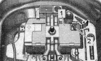
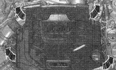
Remove the "arrow" engine cover.
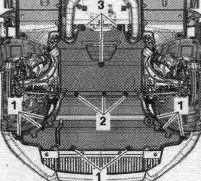
Remove the noise insulation "1" from the left and right in the wheel arch.
Remove the sound insulation by unscrewing fasteners "1...3." If the unit mount, steering gear, or subframe crosspiece is not properly mounted, the vehicle will not be able to be driven.
Unscrew bolt "1" of the hydraulic line of the power steering.
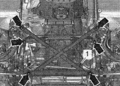
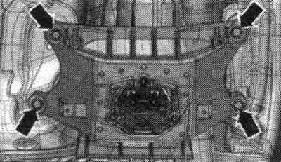
Unscrew the arrow bolts and remove the subframe spacer crosspiece.
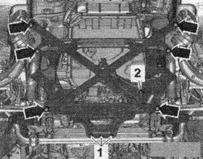
Remove the exhaust pipe and diesel particulate filter.
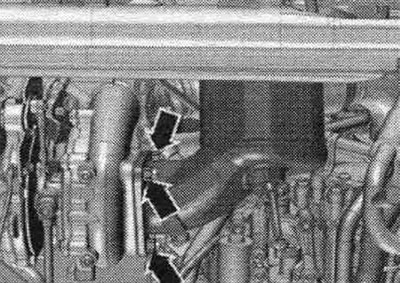
Unscrew bolt "3" of the connecting rod from above. "Pos. 1, 2" do not take into account.
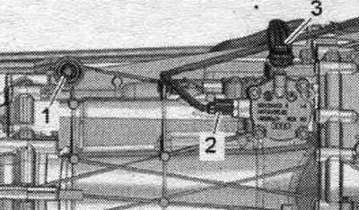
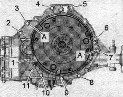
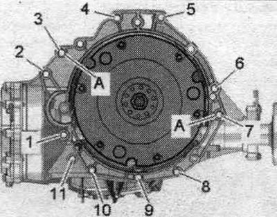
Unscrew the bolts "2...6" that connect the gearbox and engine and are accessible from above.
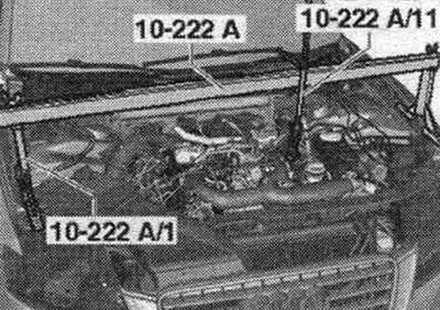
Install the traverse "10-222 A" together with the frames "10-222 A/1" and the lead screw "10 222 A/11" as shown in the figure.
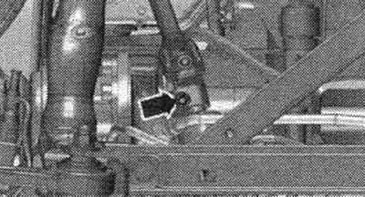
Disconnect the cardan joint from the steering gear only when the front wheels are installed straight. wheels. Do not change the position of the steering wheel or steering gear; if necessary, secure the steering wheel with duct tape. Unscrew the "arrow" bolt of the universal joint. Press the steering gear cardan joint and move it fully upward.
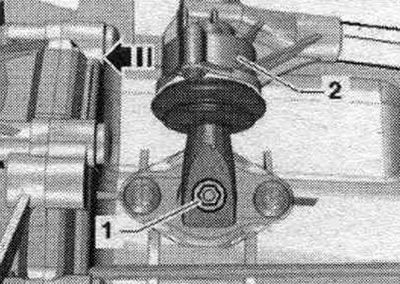
Engage 6th gear by removing shift shaft "1" and shifting gear lever "2" forward in the "direction of the arrow".
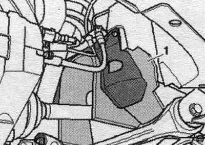
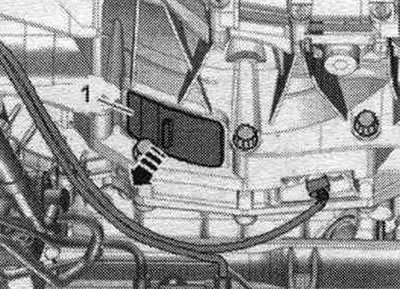
Remove cover "1" under the gearbox "arrow".
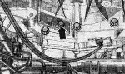
Unscrew the 6 bolts "arrow" of the clutch module on the driven disk, to do this, turn the clutch module/driven disk using the front. wheels respectively by 60°.
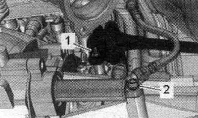
Unscrew bolt "2" and tie the clutch slave cylinder to the side of the motorcycle. compartment. On the clutch pedal after removing the working cylinder. do not press the clutch. Unscrew nut "1".
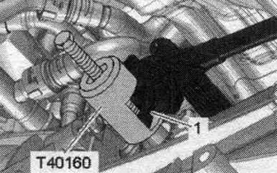
Install the puller "T40160" and remove the gearbox lever "1".
Unscrew bolt "1" of the starter from the engine side. Remove the starter from the gearbox and leave it in the mounting position. position. Unscrew the remaining bolts "7...11" connecting the engine/gearbox.
Install the tilting device with the mounting bracket "T40173" under the gearbox and secure it with the harness "1", as shown in the figure. Unscrew the tunnel cross member arrow bolts.
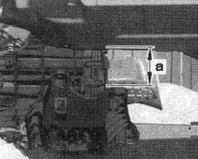
First, lower the CP using a tilting device by the value "a". Dimension "a" = maximum 100 mm.
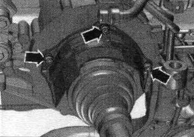
Pre-tighten the engine lightly with the 10-222 A/11 lead screws. To access the 10-222 A/11 spindles with the vehicle raised, use the VAS 5085 step ladder. Loosen the arrow bolts and remove the right drive shaft heat shield. Unscrew the left and right drive shafts from the shafts with the gearbox flange.
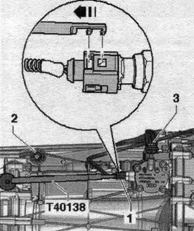
Disconnect and release the connector "1" of the gear position sensor "F208" using the puller "T40138". Unscrew the bolt "2" of the push rod. "Pos. 3" should not be taken into account.
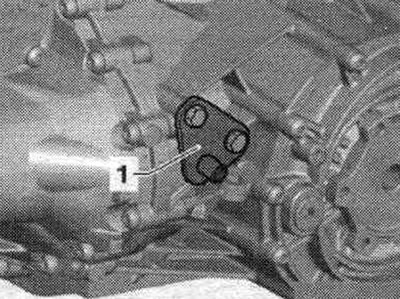
Press the gearbox away from the engine and carefully lower it using a tilting tool. In case of replacement of the removed gearbox, it is necessary to move the following parts to the new gearbox: bracket "1" of the support bar of the system. exhaust system, tunnel crossmember with gearbox cushion and gearbox support.
If necessary, remove the clutch module.
(The original material is located on the website AudiManual)