
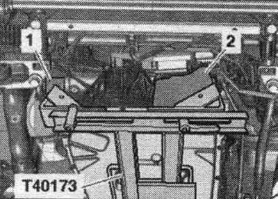
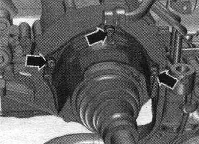
Install a powertrain lift with the prepared "T40173" transmission mount under the transmission. The front transmission mount must be installed as follows: on the left side, mounting block "2" fits into the flywheel hole in the transmission housing; on the right side of the gearbox, the elastic gearbox mounting gasket "1" touches the central differential housing.
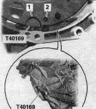
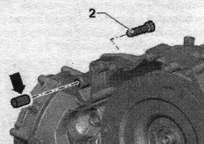
Secure the gearbox using tension belt "1". Before connecting the engine and gearbox, perform the following preparatory steps. Install the auxiliary mounting device "T40169" from below into the gearbox housing and into the flywheel, as shown in the figure. The mounting fixture should fit into the semicircular groove "1" and additionally into the inspection hole "2". There is one inspection hole around the perimeter; turn the flywheel accordingly. Insert mounting bolts. devices into the hole on the gearbox housing.
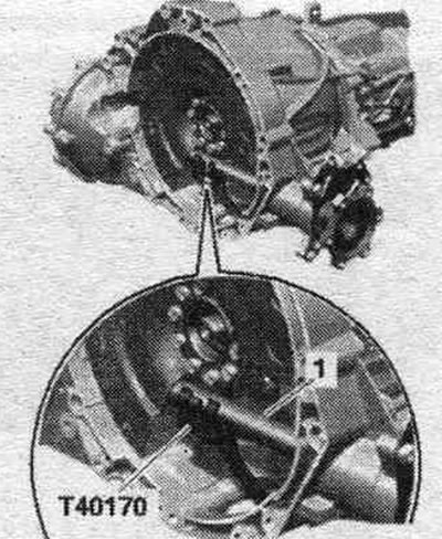
Install the "T40170" transport guard underneath the gearbox housing and attach it to the shaft with flange "1." Check the aluminum engine-to-gearbox connection bolts for reuse and mark them if necessary.
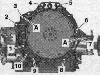
Vehicles with a 4-cylinder petrol engine: Check the presence of centering bushings "A" for the engine and gearbox in the cylinder block; insert the bushings if necessary. Place the engine against the gearbox and tighten bolts "6" and "7" connecting the engine/gearbox.
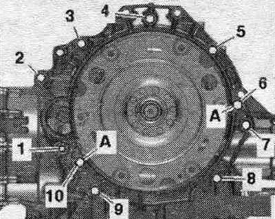
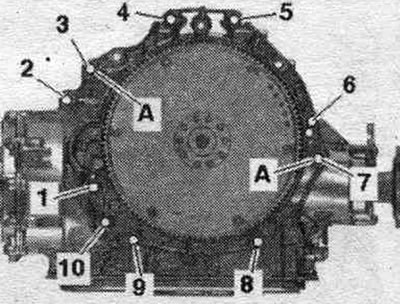
Vehicles with a 6-cylinder engine: Check the presence of centering bushings "A" for the engine and gearbox in the cylinder block; insert the bushings if necessary. Place the engine against the gearbox and tighten bolts "6" and "7" connecting the engine/gearbox.
All
Screw on the tunnel type cross beam. Lower and set aside the lift with the "T40173" gearbox mount. Tighten the engine-to-gearbox mounting bolts, accessible from below. Remove transport protection "T40170" and mounting device "T40169".
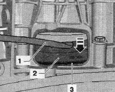
The next stage of work is necessary to ensure uniform fit of the flywheel to the driven disk without distortion. Press the flywheel "2" using the mounting. lever "1" to driven disk "3" "arrow".
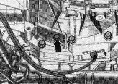
D/m with 4-cyl. petrol engine: Use a ring spanner SW 16 to tighten the bolts "VAG1332/14". Tighten the flywheel bolts on the driven disk as follows: Screw in the first bolt "arrow" by hand (2 Nm).
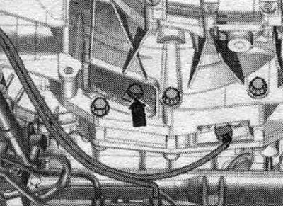
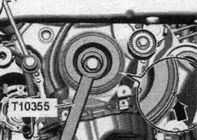
Turn the crankshaft by the torque converter using the counter support "T10355" by 240° in the direction of engine rotation. In this position of the crankshaft, tighten the accessible bolt. given moment. Next, turn the crankshaft by 120° and tighten the remaining 2 bolts to the specified tightening torque. "Arrow" should not be taken into account.
Cars with 6-cylinder engine: To tighten the bolts, use a 16 mm ring spanner - VAG 1332/14-. Tighten the flywheel bolts on the driven disk as follows: tighten the first bolt "arrow" by hand (2 Nm).
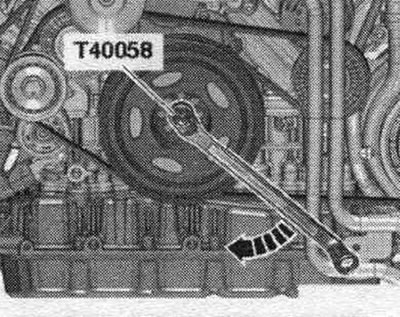
Insert the guide pin of the adapter "T40058" as follows: the large diameter "arrow 1" faces the engine; small diameter
"arrow 2" is directed towards the adapter.
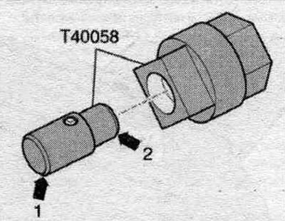
Turn the crankshaft of the vibration damper using the adapter "T40058" 180° in the direction of engine rotation "arrow". In this crankshaft position, tighten the accessible bolt to the specified torque. Next, turn the crankshaft by 60° and tighten the remaining 5 bolts to the specified tightening torque.
All
Installation in reverse order. Bolt the intermediate steering shaft to the steering gear. Install the selector cable drive. Install the ATF lines. Mount the left and right drive shafts onto the transmission flange shafts. Install the drive shaft heat shield. Install the cardan shaft.
Cars with a 4-cylinder gasoline engine: Bolt "2" secures the starter to the gearbox and is additionally equipped with a spacer sleeve "arrow." The spacer sleeve must be installed between the starter and the gearbox.
All
Install the starter. Tighten the remaining bolts "3...5" of the engine/gearbox connection. Install the system. exhaust gas outlet and secure without mechanical. stresses. Install the front wall of the water drainage box.
A/m with hydraulics. power steering: Install the power steering hydraulic lines.
All
Install the subframe cross braces. Install diagonal braces. Install the PTO shaft covers and sound insulation. Perform the necessary steps after connecting the battery. Check and adjust the selector cable.
A/m with hydraulics. power steering: Fill the power steering hydraulic fluid.
All
Checking and adjusting the ATF level. Check the transmission fluid (MTF) level and add more.
Tightening torques (Nm)
| Bolts and nuts | M6 | 9 |
| M7 | 15 | |
| M8 | 20 | |
| M10 | 40 | |
| M12 | 65 |
PTO shaft heat shield - tightening torque
Tighten the drive shaft heat shield arrow bolts to 23 Nm.
Dual clutch transmission with 4-cylinder petrol engine
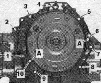
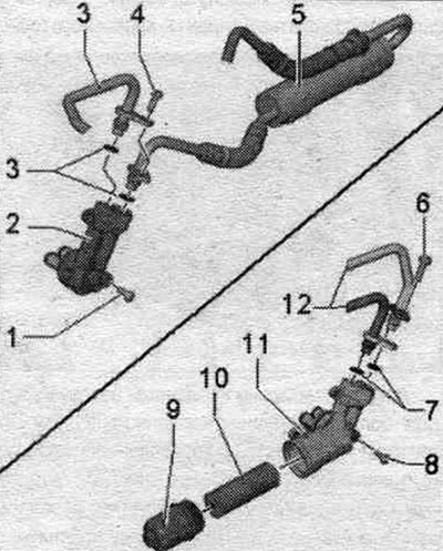
| Pos. | Bolt | Nm |
| 1 (1) | M10 x 60 (2) | 65 |
| 2 (3), 7 | M12 x 100 (4) | 30 + 90° |
| 3 (5), 6 | M12 x 75 (4) | 30 + 90° |
| 4, 5 (5) | M12 x 120 (4) | 30 + 90° |
| 8, 9 | M10 x 75 (4) | 15 + 90° |
| 10 | M10 x 60 (4) | 30 + 90° |
| A | Centering bushings | |
Dual clutch transmission with 6-cylinder petrol engine
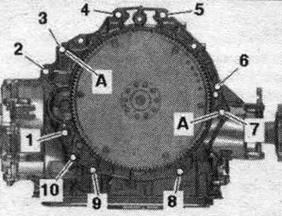
| Pos. | Bolt | Nm |
| 1 (1) | M10 x 50 (2) | 65 |
| 2 (1), 4...6 | M12 x 100 (3) | 30 + 90° |
| 7 | M12 x 125 (4) | 30 + 90° |
| 8 | M10 x 60 (4) | 15 + 90° |
| 9, 10 | M10 x 95 (4) | 15 + 90° |
| A | Centering bushings | |
Dual-clutch transmission on a 6-cyl. TDI engine
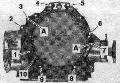
| Pos. | Bolt | Nm |
| 1 (1) | M10 x 50 (2) | 65 |
| 2 (1), 4...b | M12 x 100 (3) | 30 + 90° |
| 7 | M12 x 125 (4) | 30 + 90° |
| 8 | M10 x 60 (4) | 15 + 90° |
| 9, 10 | M10 x 95 (4) | 15 + 90° |
| A | Centering bushings | |
(1) Additionally secures the starter.
(2) The bolt hardness is 10.9, the steel bolt can be used repeatedly.
(3) Additionally secures the starter; equipped with an additional spacer sleeve between the starter and the gearbox.
(4) Bolts can be used twice.
(5) Additionally secures the wiring bracket
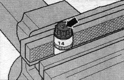
Aluminum bolts "2...10" can be used twice. Therefore, after the first use, mark such bolts with 2 notches "X" "arrow". To avoid damaging the bolts when making the notches, do not clamp them in a vice. Insert the bolt as shown in the illustration into the 14 mm socket using a 1/2-inch drive, which can then be clamped in a vice. Do not reuse bolts marked with "X".
[The original publication in its entirety is posted on the website AudiManual]